Sunbeam ~ C-Dory 22 Cruiser

First, Sunbeam and I have corresponded off line on this subject and related issues.

I feel that the U 1 battery is undersized to start any outboard of 70 to 90 HP. If the battery is topped off, and is in ideal condition, it will probably start it--just like a jump start pack will. But if the battery is older, a bit sulfated, is very cold, or has to turn the engine over a number of times, it will not be sufficient. The minimum size starting battery for a Yamaha 90 is 380 CCA.

I don't also agree with either it will or it will not as the only criteria.. If you have an undersized battery and you are straining it--both the battery and starter motor will suffer. Starting draws a lot of amps. This create heat in the starting motor and low voltage can harm it. CCA or MCA are difficult to measure and there is a bit of hocus pocus in the battery industry about this measurement.

The U1 is a garden tractor battery--it is designed to start a 10 to 25 hp engine. It has 35 amp hours; the weight is about 17 lbs. Compare to the group 24 which is the usual battery which a C Dory comes with: (The group number just refers to the case size, and there can be various specs in that group--so I am choosing a range--70 to 85 amp hours, CCA or MCA (how much current can be delivered in 30 seconds until the voltage drops to 7.2 volts, CCA is at zero degrees and MCA is at 32 degrees F.) A group 24 can run from 500 to 1000 MCA, and weight can be from 35 to 50 lbs. What does the higher weight mean? More lead, and more capacity! So if you are out there, and you want that engine to start--do you want 200 MCA or 1000 MCA? I'll elect the 1000 MCA 50 lb battery any day of the week.

The group 31 battery will run up to over 60 lbs, and with more capacity. There is a school of thought on our size boat that you use one size--say the group 31 because you need a good amount of house amps for the lights and maybe a refrigerator. Run one as the starting battery and the next day run that as the house battery. More even utilization. My C Dory came with two group 27's and I will use them until they are gone, then go to 31's.

The question of not fully charging a battery has been answered by Boris--these outboards are not "smart chargers" and it takes hours to get the battery fully topped off. Thus when cycling a few hours a day you are running somewhere in the 80% max charged range if just using the outboard. For example the charger I use for my group 34 battery I cycle my freezer on has temperature compensation, it shows the volts and the amps delivered. Even after several hours the smart charger is delivering several amps. When it starts it is at 30 amps, then gradually decreases as the voltage and internal resistance of the battery allow. Batteries accept initial charge rapidly--this is about 70%, the last 30% takes hours in the float stage---this is why you do not fully charge the batteries with the outboard motor. If you pull into a dock every few days, and run the charger on mains power, then the battery will last longer, and give you better power curves.

I am going to be a bit simplistic when discussing the over charging of the small battery. An outboard alternator generally puts out about 14.4 volts. This is constant. As the smaller U1 starting battery comes up rapidly--and the VSR opens to charge the second much larger battery. However 14.5 volts is the margin where a battery can be damaged by over charging. If the larger battery is still absorbing the current, it will not be over charged. The smaller battery is heating up, and can be damaged by over charging as it is exposed to the 14.4 (or higher voltage--I have seen some over 15 volts) Now if you have a temperature sensitive relay and could cut off the charge when the small battery heated up--that would work fine. Quality battery chargers have just such a sensor and cut out.

The best bet is to have equal, or near equal size batteries for house and starting when using a simple system charging off the alternator of an outboard. I agree with the top off with the battery charger every few days.
This is the keep it simple system.

There are down sides to the ACR or VSR--and one is that they will combine the batteries when charging. They do draw current. A simple way is to disconnect them physically (switch) or disconnect the battery cables when you are not using the boat for a period of time.

As for cruising sailboats...even in the 1980's we had very sophisticated gear aboard--even before GPS--there was Sat Nav, LORAN, Radar, Weather FAX, SSB radios, Ham radios, and even had Omega navigation systems. Washing machines, water makers, large holding plate freezers, auto pilots etc, took lots of power. The first boat I thought it would be more efficient to put a 200 amp 12 V alternator on the main and a 200 amp 12V alternator on the genset (I suspect I had more batteries than Boris did with 1400 amp hours). We had to use a Spa Creek field current system to bring the genset alternator on line and regulate the voltage and charging rate. The second and smaller cruising boat (but still had 1200 amp hours of batteries, we sized the generator to run every system on the boat at once, and thus used two 150 watt chargers on the 110 circuit.
 
thataway":3m2fys6w said:
I feel that the U 1 battery is undersized to start any outboard of 70 to 90 HP.

I agree and that was my mistake. I'll look for a battery with more CCA. I certainly don't want to strain my nearly-new Yamaha! I for some reason thought the U-1 had more like 300 CCA, and so I didn't think it was that under-rated (because I did look up the Yamaha specs before buying it). I clearly goofed, and I will replace it with a battery that has more CCA. I'm glad I got this figured out now.

As for the rest of the system, I'm a bit torn and somewhat despondent about it. On the one hand, it sounds like it should work well, and when it's explained to me by the designer or by Blue Sea I get the logic. On the other hand, you obviously know what you're talking about, and you recommend the "manual" 1-2-Both switch and two matching batteries. Normally I don't go in for "black boxes," and maybe that's what I've done with this "new-style" system with the ACR (?) Now I find out it can draw power when the switch is off (sure I can wire in another switch, but .... ugh). I really don't know which way to go now and I don't really completely understand it for myself and that is a feeling I don't like.

Another factor is that planned to have both batteries in the starboard lazarette, and didn't want the weight of two Group 31's in there. My boat is likely already going to be starboard-heavy, and that would make it worse. Bleargh. Let's just say I'm not a happy C-Dory owner tonight.

thataway":3m2fys6w said:
As for cruising sailboats...even in the 1980's we had very sophisticated gear aboard--even before GPS--there was Sat Nav, LORAN, Radar, Weather FAX, SSB radios, Ham radios, and even had Omega navigation systems. Washing machines, water makers, large holding plate freezers, auto pilots etc, took lots of power.

Sounds like your boats were in a different league than what I was on. For me a "big" house bank was around 350 amp hours, but our loads were pretty simple. We had RADAR and SSB, but no refrigerator, no pressure water, no water heater, etc. Basically just lights when at anchor, plus a propane solenoid, and then later some computer use and camera battery charging. We were pretty parsimonious as we only had limited ways to put the energy back (one solar panel, a wind generator, a smaller engine alternator that we didn't like to use when not underway). I guess the downside is that I did not become as proficient as I might have at electrical systems.

Sunbeam
 
Rob & Karen":1cq4bl3v said:
Sunbeam,

I have pretty much the same setup as you. ... The boat came with a 1-2-All-Off switch. I got tired of fooling with the switch while on the boat and changed to the new battery switch you have with the ACR. I think it was in the second year of owning the boat that I added the new switch and ACR, so I have 3-4 years of use with no problems. I really like the setup and would certainly add it again on a new boat.

Rob,

I missed your post earlier, I guess because there were a few other posts around the same time. I appreciate the info so I wanted to reply to say thanks. Really, I'm completely confused now, and have been wondering whether I should just take out the new stuff and go back to the old setup (1-2-Both switch and two Group 24 flooded batteries). On the other hand, it sounds like what you have is similar to what I added, and is working, which is good to hear. But then you are hooked up to a charger much of the time - maybe that's the difference?

Sunbeam

General PS: I looked at the battery chart of the company whose batteries I got (Full River). They have a deep-cycle AGM U-1L with 350 CCA at 0º F -- maybe that's what I thought I was ordering. It's a lot closer to the 380 CCA Yamaha recommends, and I remember thinking "well it's a few less but pretty close." Upon looking over their website more tonight, I see they have a "cranking" AGM U-1 with 438 CCA at 0º F. That sounds more than ample, and a cranking battery sounds like a good idea for a start battery - unless that is still too mismatched, or you can't combine cranking with deep cycle in the same system (I thought I knew, but ... who knows anymore). I'd like to stick with the U-1 if it will work well, because of the lower weight; but not if it's not "good."
 
Sunbeam
Thanks for great thread of your travels thru C-Dory referb and personalization. You are on a similar course to me. I've had my 22 for 2 years now but only recently with my semi retirement I've had time to get started w/ my boat projects. Now I don't have money to do it!! Thus is life! I'm lovin it. Ive been taking pics and soon I'll get them up. I too feel much more comfortable with fiberglass and epoxy work but I'm way behind you in electrical.
So thanks for your blow by blow account. Your last bit with Dr Bob, Boris and the others who are way ahead of us has been most helpful. Your angst has been felt but it has been a really great learning chance for the rest of us.
Dr Bob's thoughts about using two batteries the same and switching back and forth with house and engine sounds simple and makes sense. Something more for me to study up on.
So thank you and steady on!
Michael
 
Hi Michael,

Nice to hear about your 22 and how things are going with it. I hope you'll post more about your projects (it's fun to follow along), and maybe some photos too :) I'm glad you're getting some useful info from this thread.

**************

Now I think I'll post about something that I understand, which is taking care of the core on my 22 so that it stays nice and dry (how I like it :D). I was going to wait to post until this was finished, but since someone asked about it, and since it is basically "structurally" done, I figured I'd bring anyone interested up to where things are now.

When we last saw the transom drain in my 22 Cruiser, I had removed the original brass drain tube (which seemed to be installed straight onto the bare balsa core, with very little sealant) and eliminated the very small bit of damp core that was just beneath it. (Then I put the project on hold while I did the splashwell drain tube.)

I wanted to replace the transom drain with something that was corrosion resistant (brass is not, especially in salt water, where I would like to be able to spend some time), and I also wanted the core to be protected, with no nagging, "Well I think it's probably good" on my part while I was relaxing at anchor. A bonus would be a piece of hardware that was easily replaceable, if I used something that might ever need replacing. After considering the various options I came down to two top choices:

1) Basically re-create the function of the brass tube but with a pre-formed fiberglass tube. Difference from the original install being that I would cut out the core for a certain distance around the perimeter, fill that with thickened epoxy, and then also bond the tube in with epoxy. That would then take the usual "Thermos bottle stopper" style of drain plug that goes into the brass tubes (1" ID tubing; 1" plug).

2) Close out the core entirely and use one of a number of available garboard drain fittings (basically a flanged fitting with a screw in plug).

At first I leaned toward option #1, but I was still undecided. So I decided to switch gears and do the splashwell first, using the fiberglass-tube method. Since there really isn't the option to close out the core in the splashwell, option #1 was my choice there (protecting the core with a wide annulus of thickened epoxy around the tube, and then bonding in the tube as well).

After re-doing the splashwell drain, I felt good about the fiberglass tube method, so from that angle I was good-to-go with it for the transom drain; but I decided I still wasn't totally keen on the "Thermos stopper" plug style. Not that they don't work fine, but using an existing one is different from choosing to install one vs. something else when you are starting from scratch either way. Since I was trying to decide between the two options, I had to choose somehow, which came down to details and preference.

Ultimately, I decided to go with option #2. I decided on a basic concept (knowing that it might change slightly as I went along), which was that I would remove the core completely from the area where the drain tube had been, add layers of fiberglass for strength and to close out the new edge of the core, and then ultimately install some sort of garboard-drain style drain. No worries about core, plenty of strength, and a drain plug I felt confident in - and which could be replaced easily in future, if needed or wanted.

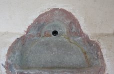
Here is a photo showing the original transom sump. It's depressed, but fairly shallow, and there is still core under it - it's just thinner than the main hull core. You can see the brass drain tube from before I removed it, and also that I removed the fuel tanks and cleats and epoxied those holes, along with a few where the bilge pump hose was attached to the transom.
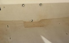
1_aft_sump_original.jpg

I pencilled in a "sunrise" shape on the transom, inside of which which I wanted to remove the core and the inner skin - leaving the outer skin intact. I planned on enough room for an epoxy fillet and then for the glasswork join the transom again and flatten out in the center. I needed to keep the transitions gradual enough so that fiberglass would lie nicely over them (it does not like abrupt transitions). My plan was to cut the area out in rough sections with the Multimaster, pop out the skin-and-core "pie slices," and then finish the cut by sanding to the line and shaping with a Dremel tool.

In "wait and see what I find" mode was whether I would leave it at that, or whether I might cut the core out of the whole sump, to make it slightly deeper for the bilge pump. I figured I'd see how it looked when I got the first part cut out. In favor of leaving the sump shallower was that the drain plug would be the lowest point; on the other hand, the deeper sump would have advantages too. Sometimes I just have to get into something before deciding on the final details.

Before starting to cut, I cleared and protected adjacent areas, and taped a vacuum hose nearby to catch dust. I taped over the drain hole on the outside of the boat. Then I donned my regalia and dived in.

Here I have made the first cuts. You can the penciled in "sunrise," and also a small dark circle in the sump - that's one of two holes I over-drilled and filled earlier, that were left over from where a bilge pump was screwed down (right into the core… thankfully dry). (The bilge pump in the galley sump was held down by blobs of caulking, so no fasteners into the core.)
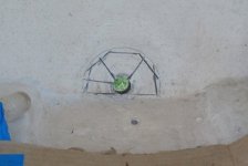
2_beginning_cuts_inside.jpg

Here the upper "sunrise" shape has been removed, and I'm mulling over how to handle the bottom section. I like how the drain hole will be at the very lowest point, but I'm also thinking about how to make nice smooth fiberglass transitions, and I would appreciate a deeper sump.
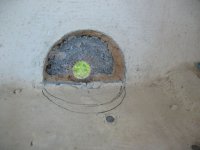
3_upper_section_of_hole_with_core_removed.jpg
I decided to go ahead and cut out the sump. In the short, project term, it would make for nice fiberglass transitions, and long term, I'd get a deeper sump out of the deal. When I cut around the perimeter, I left the rounded edge of the top skin where it had originally turned down into the shallow sump, because it would make a nice shape for the new glass to follow as it "fell" over the curve; then fillets would complete a gradual turn onto the flat bottom area. Likewise I didn't cut the two after corners square - that would have been awkward to 'glass. Here it is mostly cut out - the wide band around the edges where I have removed the gelcoat is where I will overlap the new fiberglass. I did further cut out and shape the after corners where they transition into the vertical transom, but that was after this photo (and I didn't take another one before filleting). You can see here how the original sump is also cored, but just with thinner core than the main part of the hull.
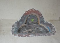
6_full_cutout.jpg

Some of the removed core and also a piece of the inner skin with core attached. The core was all dry, and the core/skins were well bonded.
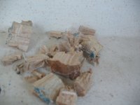
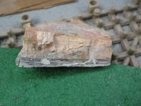
4_some_of_the_core_removed_dry.jpg

5_showing_thickness_of_laminate.jpg

Next it was time to fiberglass. Well, no, make that time to prep for fiberglassing. I sanded until everything was smooth, and then vacuumed and tacked off. I wanted the finished product to be reasonably neat and tidy, so it would look good and be easy to clean; but given the finish of the rest of the adjacent area, I didn't have to strive for the perfection I would have if this were a molded part of the boat. Next I made patterns so that I could cut out the various pieces of 'glass. One way I make them is to take clear plastic and lay it over the area, then mark the outside perimeter right on the plastic with a Sharpie marker. Then I cut out the plastic pattern along the lines and use that to mark the largest pieces of fiberglass. After that the pattern can be cut smaller and smaller to mark subsequent pieces. I then laid the pieces out on waxed paper for wet-out, in such a way that I could remember what went where. Here is the glass before I organized it a bit better for wet-out.
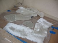
8_stack_o_cloth.jpg

Next the the various epoxying tools were assembled (mixing cups, stir stick, epoxy/hardener, colloidal silica, squeegee, chip brush, roller, and various shaped pieces I cut out of milk/water jugs (the latter are very handy, free, and customizable). Then I mixed up a batch of neat epoxy and used that to wet out the fiberglass pieces and the sump area. I just pour the resin onto the cloth and then spread it roughly onto the cloth at this stage, because once it spreads out I have lots of working time (vs. when it's concentrated in the cup). While it sits there on the cloth it does a lot of the work of soaking in on its own. Meanwhile, I thickened what was left to a peanut butter consistency so that I could use it for filleting. The fillet provides the gradual "ramp" transitions that fiberglass cloth likes.

Speaking of the cloth, and curves and transitions. One good method for making cloth lie nicely across curves is to run it on the bias, which basically means diagonal to the weave. Of course the "problem" when you have compound curves is that it can't run on the bias for all of them at the same time. For this reason I started by making shorter pieces that could run mostly along one edge (on the bias) and then just around the corners to the point where it got finicky. Then the next piece would do the same thing and they would overlap. The main cloth I used was 4" 15 oz. biaxial tape. With biax, the fibers already run and cross at diagonals, so it was happy to lie down even when run "straight," but of course I still couldn't run it all the way around in one piece and have it lie down well. (The main reason biax is made with the diagonal crossing of the fibers is so that when you use it for tabbing or some placement where it runs across a gap or edge, you still get the strength of all the fibers. With a 90º weave half the fibers aren't really doing much where they cross the gap. Not that that was my situation on this project).

So anyway, back to the cloth, I had cut lengths of the biax to run all the way around the edges with overlaps between sections, and then cut additional pieces that would lie on the bottom and transom so that I would end up with at least three layers everywhere. Then I cut larger pieces of 10 oz cloth to lie over the top of everything, just because it's a nicer finish layer, and it was thin enough that I could coax it into place with fewer joints. I also decided to place Peel Ply over the top of the whole works. PP is a nylon fabric - sort of like a windbreaker - and it not only leaves a nice finish, but with it in place you can really "work at" the cloth without disturbing it or picking up fibers. Not that it's a big deal to wash off, but it also takes off any blush when you peel it away. I don't use it on everything, but just sometimes.

Okay, back to our epoxy (one can be so leisurely with it when typing :D). I used the thickened epoxy to lay in a good fillet on all the edges so that the cloth would not have any sharp transitions.
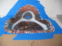
7_wet_out_and_filleted.jpg

Now, sometimes you want to let the fillet really set up before you proceed, but in this case I was fine to go ahead and place the cloth with it just slightly firm. I was mindful not to "crush" the fillet or displace it as I worked. I got all the biax layers in place, and then used the roller (a metal, grooved roller) to roll around and get the air out. Biax really likes to hold air, and although you can poke at it with the bristles of a brush, or push air out by hand or squeegee, the roller works really well. I still had areas where I couldn't use the roller because it wouldn't fit, so there I had to do it by the other methods. Anyplace that cures with trapped air is not good, and may need to be cut out later and re-glassed or filled depending on size/location - so it's best to avoid that. Once I had the air out, I then placed the 10 oz cloth over the top, and then the Peel Ply, after which I smoothed it out one last time and then let it all cure to the green stage (not soft or really tacky but you can still dent it with a fingernail; this often seems to be at 3 a.m. ;)). Then I removed the Peel Ply and trimmed any obvious edge strands, because that's easy while it's green. That left me with this:
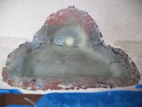
9_fiberglassed.jpg

You can fair while in the green stage, but in this case I wanted to let it cure and then sand it before fairing. After sanding I vacuumed and tacked and then faired with a mixture of epoxy, microballoons, and a touch of colloidal silica (helps it to spread smoothly).
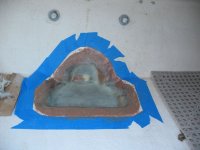
10_faired.jpg

After that cured I sanded it smooth again. All the sanding/fairing stages are much easier if you are reasonably tidy in your epoxy work, so there are not great gross gobs to deal with. It also helps to sand it just when it's hard enough, but not wait much longer (it continues to harden and so gets harder to sand).
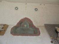
11_faired_and_sanded.jpg

Then I seemed to have my first epoxy failure. Yes, I was trying something new without making a test panel first - my bad! Here's what happened. First of all, there is "common knowledge" that gelcoat (polyester) won't stick to epoxy. I wanted to gelcoat the sump, if possible (vs. painting it), for various reasons. The Gougeons (WEST System) had written up some tests that showed good adhesion of gelcoat over well-cured and -prepped epoxy. Yes, they do make epoxy, but they also generally do good, repeatable experiments and tests.

http://www.westsystem.com/ss/polyester-over-epoxy/

What I wasn't sure about was the definition of "well cured." Were they talking days? Weeks? Months? I called up their tech department to ask. They said probably more like days/weeks, not months, and then they also mentioned that it would help to have a slightly resin-rich epoxy mix, or at least not hardener rich, for the last layer. They explained that any "left over" hardener molecules (that didn't find resin to bond with) are what can really affect the bond. I often like to go over a faired area with one last coat of neat epoxy anyway, so I figured fine, I'd just make that batch slightly resin rich. I then decided to add some WEST white pigment, because I'm at a friend's place and he had some available. The microballoons are a sort of dark reddish-purple, and although the epoxy pigment is more of a "wash" than a solid color, it would at least help me along, color-wise.

You know how problems usually have a chain of mini-issues that add up… well, another little thing that would not have been a problem in and of itself was that I had run out of fast or medium hardener, so I only had slow hardener. It was not really cold out (low 60's), but a bit cooler than ideal for slow hardener (just means it takes longer but this would become a factor later). Well, I had other projects to do while it cured, so no big worry that way. I mixed up a batch of neat epoxy, just slightly resin rich (that felt weird, as I usually try to make it just exactly right), and then added the maximum (but no more) proportion of pigment. Then I brushed a coat onto the new sump.

I had leftover epoxy, and all the time in the world to apply it (because of the slow hardener), so I decided to do a few other jobs with it. I laid in a fillet in the anchor locker with a strip of cloth over it (between the bottom and the bulkhead). This both glassed over a hole in the bulkhead (there was a mini eye-nut there that I removed) and made for a smooth, cleanable transition (before it was a bit sunken, rough, and low). Then I went around and dabbed some on all of the former holes into the core I had filled and wanted to gelcoat later (some in the cabin where there were L-brackets holding the cabinets to the sole, some where the fuel tank cleats were, some where bilge pump hose was attached to the inside transom, and some where the swim-platform ladder was attached).

Here is the sump after the coat of pigmented epoxy.
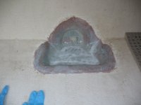
12_coat_of_resin_pigmented.jpg

You probably know where this is going….

Next day, still tacky. Well, that's not unexpected, with the slow hardener and cool nights (50's). Next day… still tacky. Hmmm… Next day…. tacky. Uh-oh. I applied some heat (carefully) with a heat gun on low. Finally the next day (still tacky!) I called WEST's technical line and explained. I did mention that although I had used the WEST pigment, I was using System Three epoxy. Although I have used a lot of WEST over the years, I find it less easy to carry along when traveling, due to the pumps. With a 2:1 mix ratio like System Three uses, I can just carry the sealed containers and use mixing cups. They were very gracious about it and said that System Three was also a very good epoxy and to go ahead with my question. At first they couldn't think of what might have gone wrong. I retraced my steps with them and then the light bulb went on. Apparently (although I didn't see this anywhere in the literature) the pigment is basically resin. So first I made my batch slightly resin rich, and then I added…. more resin!, in the form of pigment :cry It seemed as though perhaps the resin molecules were just running out of hardener molecules to bond with. Bleargh.

I waited a couple more days and then decided to call System Three, since it was their epoxy I used. I explained again, and my main question this time was…. what were the chances it would ever harden if it was still soft now (I had saved about an inch in the mixing cup and it was still "smooshy"). They said, well, slow is really slow in cool weather, and they recommended that rather than the shorter-duration heating of a heat gun, that I use something like a space heater and heat the area up to around 80º-90º over a longer period of time (overnight, say). So I did that for 12 hours in both the anchor locker and the transom area. It firmed up slightly but was still not cured. System Three said that they could see where it might just not cure, but… it also might.

Well after more than a week had gone by I was just sick of waiting and worrying about it, so I decided to simply remove it and be done with it so I could move on. That wasn't great fun, but it wasn't that bad either (albeit discouraging at the time). I mostly used a sharp cabinet scraper, with a bit of chiseling in the anchor locker (where I had a fillet and cloth). When I was all done nothing looked any worse for the wear and it was all back to where it was before the last epoxy application. Whew! I did save the cup with the leftover resin in it to see what would happen over time (around a month later, it's much more cured, but still a little bit rubbery, so perhaps it would have cured; I didn't want to wait around that long).

During my phone call with System Three, I also found out about an interesting product that I decided I wanted to try. It's an epoxy resin called SB-112, which was originally intended for surfboard coating. It's very clear and smooth, has more UV resistance (not that I need that), and, the reason I wanted to try it, polyester (gelcoat) is supposed to bond very well to it. In fact, the opposite of typical epoxy, you're supposed to get best adhesion if you apply the gelcoat within 16 hours, up to a maximum of 48 hours. So far I have just used it on a test panel, so can't report more than it does go on *very* smoothly and sets up quickly. I'll be re-coating and then gelcoating the test panel before proceeding on the boat.

Here is the sump after removing the tinted coat of epoxy. You can also just barely see three small holes I drilled just to let any nuisance water drain (but I left the center solid for the guide bit on the hole saw for when I re-cut the main hole).
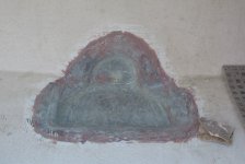
12_5_resin_scraped_off_small_holes.jpg

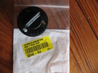
While awaiting the arrival of gelcoat (I decided to try ordering some in "C-Dory white" and "blue" to have on hand for future projects, I'll probably tint the white a bit to match the sump), I fit the new drain plug. I decided to try a Marelon drain fitting from Forespar. The plug is actually made of a slightly softer material called Hytrel™*
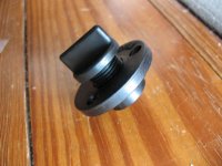
14_garboard_plug.jpg
15_garboard_plug.jpg

I like that it can be installed/removed by hand vs. with a tool. On the other hand, in case I don't like it, the pattern is the exact same one as used for many other plugs, including more traditional bronze ones.

With the plugs on hand, I drilled the hole with a hole saw, just slightly undersized, then enlarged it with a file and sandpaper, to keep it snug. Here is a view from the inside (the fiberglass here will be re-epoxied and gelcoated later).
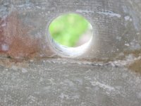
16_drain_hole_re_cut.jpg

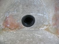
Here the Marelon fitting is are set in place to test fit. The plug is not screwed all the way in in this photo, and pardon the dust!
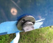
17_black_plug_set_in_place_outside.jpg

View from the inside

19_black_plug_set_in_place_overview.jpg
18_black_plug_set_in_place_inside.jpg

Alternative fitting (plug also not screwed all the way in).
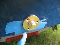
20_alternative_bronze_plug.jpg

And that's where things stand as of now. It's okay to pause at this stage because it's all waterproof, there isn't any UV to speak of getting to it, and any stray water can simply drain out the hole. Next I'll fasten the plug - but I won't bed/final fasten it until after I finish the sump. I'm getting some other projects ready for epoxy (trim tab installation), and will do some test gelcoat panels with the SB-112 before I continue with this one.

Sunbeam :hot

PS: I did re-do my work in the anchor locker as well. It was kind of a "bonus" job as I had already filled the disused eye-nut hole with thickened epoxy, but I wanted a nice smooth, easily-cleanable, for-sure-waterproof joint along that edge, so I combined that with glassing over the filled hole. The procedure was basically the same as doing the sump, although it's just a fillet and one layer of 10 oz. cloth tape so it went quickly. I made a pattern by sticking 2" blue tape in the locker where I wanted the cloth, cutting the ends with an Exacto knife, and then transferring it to the fiberglass tape (really it was just the angles on the ends that were anything but straightforward).
anchor_locker_fillet_and_tape.jpg


*"DuPont ™ Hytrel ® thermoplastic polyester elastomer provides the flexibility of rubber, the strength of plastic and processibility of thermoplastic."
 
Minor update on my starting battery: I contacted the person who helped me design the system and ordered the batteries. I remembered that the U-1 battery I got (or meant to get) had close to the Yamaha-recommended 380 CCA at 0ºF. It was slightly below that, but not by much (in the mid-300's), and seemed like a good option.

Well, as anyone who read the thread yesterday knows, when I looked up the battery on the manufacturer's chart after Thataway expressed concern, I saw it only had 190 CCA :shock: I know there's no way I would have said "Oh sure, HALF the recommended CCA sounds fine!" When I checked with the place that ordered it they too thought, "What? That's not what we remember either."
I don't know yet whether or not I will stick with a U-1 (it is a nice convenient size and weight, but I could shoehorn in a Group 24 too), but I have found a couple with much better ratings (the same brand; one of which I think is the one I was meant to get in the first place). One is a deep cycle AGM of the same series I ordered, but a U-1L and has 350 CCA at 0º F; the other is a cranking AGM U-1 and has 430 CCA at 0º F (ahh, that sounds better!).

I'm getting some facts and info before I proceed, but if it sounds viable I believe I will go with the latter, cranking AGM U-1, I'll keep the thread updated.

Sunbeam :hot
 
I'm back to make a lazarette post, but since I saw the last post was about the battery I thought I'd quickly update that first.

Although I don't have it in hand yet, a battery should be on the way that will be a good fit, both in CCA and in size. I have to give major props to Full River, the maker of both my house and start batteries. I'm far from the dealer where I got the batteries new this summer, so I looked online but didn't see anyplace even remotely nearby to get a new one. Thus I called Fall River. I braced myself for a "corporate experience," and instead got a fantastic Full River USA employee who listened to my story and - although they don't typically do this - said he would sell me a battery directly if the "shipping guys" would agree to ship it (they don't usually pack things up for individual shipment). Within an hour I had my answer (affirmative) and prices for both battery and shipping. Next day I had an e-mail and a phone call that they were on the way. Can't beat that!
On the battery: I was considering an HC-35, which is an AGM cranking battery in the U-1 size. It had around 100 more CCA than Yamaha calls for. Unfortunately, the Full River fellow said they are nearly unobtainable in the US (but popular in Europe). However, he suggested an HC-44, which is nearly as small as a U-1 and has 580 CCA (Yamaha recommends at least 380 CCA). Now we're cooking with gas :)

I'll update with some photos when it arrives and I make sure all is going to work out. Thanks again to Thataway for commenting such that I took a second look at that starting battery (which, by the way, I had not actually used to start the engine yet). I have also contacted the dealer where I bought the battery, and they are going to work something out with me (because neither of us would have ordered something that small, so something went awry somewhere along the line). So that's good too.

Now to write the lazarette post,
Sunbeam :hot
 
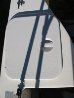
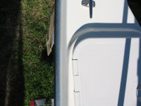
My boat came to me with the original hatches. They leaked like (apparently) everyone else's, and I also wanted to protect the core around the perimeter. So, I removed them and replaced them with a pair of the IMTRA hatches in "dream white," model number 40154. Many C-Brats have gone before me in this, so fortunately I didn't have to figure it out myself :thup I ordered them through Defender, who had them drop-shipped to me from IMTRA. All went smoothly. In this post I will lay out the steps I took, but I'm sure in so doing I will forget some details (or leave them out to keep the tome slightly less tome-y). I tried to take photos as I went, but sometimes in "the heat of battle" it's a bit tricky or I forget. Another note is that in fiberglass work there is usually more than one good way to go about it, so this is just the way I chose to do this particular job, given the givens.

Removing the original hatches (which leaked) was a bit of a pain because they were held down with gobs of silicone :amgry, but eventually I prevailed and got the area cleaned up. When I laid the hatch rims (until you install the hatches you can separate the lids from the rims, but not after, which is slightly too bad) (there is also a template included) on the existing openings, I could see that the fit was not going to be very good at all. In order to encompass the existing opening, I would have had to set the hatches somewhat askew (thus overlapping part of the molded-in "boss" of the deck), and even then there would have been just a tiny bit of deck under some of the hatch rims (if that), which would mean that there was no mating surface for bedding compound. Not good! The reason was that the original hatches were slightly larger, and then the holes were cut a bit on the large/sloppy side even at that. The forward and after ends fit pretty well, but the long sides is where the problem existed.

I determined that by adding about an inch or inch-and-a-half of new material along the inboard long side on each opening, I would have a good fit and placement of the new hatches. As part of the job, I would be digging out the balsa around the perimeter (which was dry, thankfully, but I'm not confident it would have been if my boat had not always been stored in a building) and re-filling with thickened epoxy. Also, while the original hatches were held in by (pointy) screws just into the core, I would be fastening the new ones with machine screws (through fastening).

Here the core is being dug out.

1_digging_out_core.jpg

I used a Multimaster with E-Cut blade for the gross cutting, and then a Dremel and dental pick for the finish work. Then I sanded both inner lips, plus the underside of the inboard long edge where I would be adding a new section of lower skin. A vacuum cleaner was permanently set up nearby, with the nozzle taped in place to catch dust (so I had two hands for tools).

2_cleaned_out_prepping_for_next_steps_001.jpg

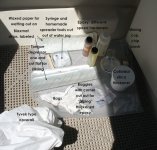
Here are some of the supplies laid out for the fiberglassing work. Not shown are blue nitrile disposable gloves, respirator, etc. On the gloves, I put four or so on each hand, taping the first pair to my suit (otherwise I always get some epoxy on my wrist!), then when I need a clean glove I just peel off the top one to reveal a fresh one. Fiberglassing is kind of like making a stir-fry: You spend the most time getting everything planned, prepped, and laid out, and then the "cooking" goes pretty quickly and is a small percentage of the job.

3_supplies.jpg

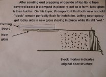
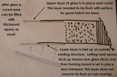
Here are a couple of diagrams to give you the big picture/plan (additional explanation below each one).

3_1_diagram_top.jpg

The above sketch shows the plan for the new top skin. It's important that the top surface end up perfectly flush (new and old) so that the hatch rim will lie flat, and bed and operate well. Thus I decided to lay the new glass on the underside of the existing deck, from which it would rise up to meet a forming board when it came past the old deck skin. I wouldn't glass like this on something structural, but for this type of job it should be more than adequate. Note also that none of the new material will show, as it will all be under the hatch rim. Thus fit and finish is only important to the function of the hatch, not to a visual level.

3_2_diagram_bottom.jpg


For the lower layer, it could be laid more "normally" and simply overlap the existing skin on the outside (underside in this case), because there is no need for it to be perfectly flush.

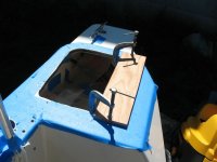
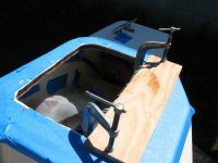
So, to begin, I protected the boat in the work area. Then I cut a piece of plywood to a size that would allow me to span the opening and clamp it past where I would be working, but not so large that I couldn't work past it. I covered it in clear packing tape, which cured epoxy will not stick to. Then I painted the underside of the existing upper skin and the forming board with neat epoxy and let that tack up (so that it would hold up the new cloth vs. letting it droop). I also wetted out the cloth. Biax can be a bit of a pain to wet out, but I find that if I first pour some resin on it and spread it out, and then go about my other business, when I come back to it it has mostly soaked in and I just have to do a little squeegeeing to finish wetting it out. I chose biax for a couple of reasons. One, I had it on hand, and two it's not a bad choice for when you are spanning a long stress line anyway, because 100% of the fibers are working for you (vs. with a 90º weave, 50% of the fibers parallel the stress line and are not doing much). That said, the layup itself was basically overkill (but no harder to lay up than if I had used thinner cloth). Next I laid the glass in place, where it "stuck" without much coaxing. I think I may have added a couple of pieces of blue tape to hold up the ends.

Here I have the forming board set in place. As you can see I was also overdrilling/filling things such as the fuel fills, rod holders, and bimini brackets.

4_adding_glass_stbd_side.jpg

Now the upper glass has been added and can cure. You can just see the rough strands sticking out past the forming board. It's left like this until it gets to the "green" stage, which is when it will no longer change shape, but is still a little bit rubbery. At that point the forming board is removed and the excess glass can be easily trimmed with a utility knife.

5_adding_glass_stbd_side_2.jpg

This next photo shows the new upper skin after some trimming. The reddish purple material is some fairing compound I have laid on and will sand back flush. Little fairing was required, fortunately. You can also see where I am filling the areas where the core was removed. I also made sure to encompass where the new hatch fasteners will go (the holes you see are the old fastener holes though). To get the fill in, I cut off the corners of baggies and use them like one of those cake-decorater frosting/piping cones.

6_fairing_new_upper_glass_in_stbd_side.jpg

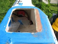
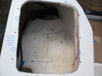
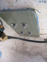
I don't have any photos of laying in the new lower skin, but what I did was similar to the upper skin, although slightly different. Since there is no need for the underside of the opening to be perfectly flush, I chose to lay the new glass on the outside (underside) of the lower skin (more conventional way). So the order of operations was slightly different, in that I got the forming board all ready but then didn't place it. Next I wet out the receiving area and let that tack up, then I laid the new cloth in place, and then I brought the forming board up underneath it and clamped it in place. When both of the new skins were trimmed and cured, I filled the area with thickened epoxy. In this next photo the area is filled, although I still did some smoothing (like in the upper right corner where it is kind of "angular" yet). Although I went back later and laid it all out nicer, I included this photo because you can see by the circled black dots where the new hatch fasteners will go, and how it would have been pretty hard to get it to sit well without adding glass. First there would not have been full surfaces for bedding compound, and second the hatch would have slightly overlapped the boat in the after/outboard corner, even at that. You can see some overdrilled/filled holes on the battery compartment bottom - that's where battery trays were screwed into the balsa core of the locker bottom. Not anymore! (The edges of the locker bottom were also raw core; those were also cut back and filled.)

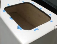
7_new_opening_almost_done_stbd_side.jpg

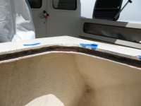
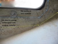
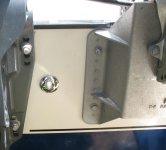
Here is an annotated view of the underside after the new hatch is fastened in place. Everything "north" of the blue line is new material.

8_annotated_underside.jpg

Similar view, unannotated. Also shows the through-fastened machine screws (untrimmed as of photo).
8_5_unannotated_underside.jpg

Overview of new hatch in place. One note on placement is that the hatch lid is actually larger than the hatch frame in certain places when it is closed. So in order to avoid any surprises, place the entire hatch to see where you want to locate it. In my case, I didn't want it to overlap the boat anywhere, but within that parameter, I wanted as much space inboard of the hatch as possible so that I could set the "ears" of a homemade splashwell tray there if I wanted to.

9_hatch_lid_overview.jpg

Here is where I wanted to make sure there was no "overlap" wherein the hatch would protrude past the raised boss on the boat. The original hatches on my boat had the hinges inboard, thus opened to the outside; I changed that because if I get a camperback I didn't want the lazarettes opening "into" a wall of canvas.

10_showing_space_outboard.jpg

As mentioned above, I did a few other tasks in the lazarettes before installing the hatches, because it was a clear, unfettered opening. I filled holes and edges on the starboard locker bottom, and I added backing plates to both stern cleats. I also put in a new battery/switch system, shunt for battery monitor, negative bus, etc. The opening isn't a whole lot smaller once you have the hatches in place, but as mentioned above, you cannot completely remove the lids then, so it's just a bit easier to work with the bare openings. The new lids will rest just slightly on the boat when opened all the way horizontal (not that you'd want to press on them then); of course if/when I get a camperback or side curtains for my bimini, they will stop against the canvas before then.

This is slightly out of order as it's from before I added the new material to the lazarette openings, but it shows the battery tray holes overdrilled and ready for filling.

12_battery_tray_holes.jpg

Backing plates were added to the stern cleats. It wasn't a high priority, but it was one of those jobs that was a lot easier to do with the hatches off and the batteries out than it would have been later! I removed around 1" of (dry) core around the fasteners and filled it with thickened epoxy, then sanded and prepped, then added fiberglass backing blocks (the material can be bought from McMaster-Carr in sheets). I set the backing blocks in thickened epoxy (this takes care of any uneven-ness; the new plates should be parallel to the deck surface). I re-bedded the cleats with butyl tape and used new 316 grade stainless fasteners. Although I smoothed the edges of the backing plates, I didn't feel that cosmetic improvements were necessary (paint, gelcoat, etc.). You can see a few remnants of blue tape where it was slightly too close to my line and got a bit stuck. It's not the easiest place to work.

11_cleat_backing_plate.jpg

If anyone is still here (!).... I imagine I have probably forgotten to mention some steps or details. I'll remember them in 31 minutes I'm sure :wink: If I can clarify anything, just ask.

Sunbeam :hot
 
Excellent job and write up! I changed my hatches, but had small enough openings to make do without having to do fiberglass. I've managed to not do any glass work so far, but I want to soon!

Our camper back stops at the forward edge of the splash well, so there's no interference with the hatch lids opening either way. Some people have more custom camper backs where the back panel allows access to the lazarettes.

I installed my new hatches so the lids flip into the motor well. The main reason was that I wanted to have a place for the lids to rest when all the way open without straining the hinges. I think my hatch openings were closer to the edge than yours are, so it's probably less of an issue for you. The other reason I flipped it was so I could get easier access to the battery switch from the dock.
 
ferret30":2ahxbphm said:
Our camper back stops at the forward edge of the splash well, so there's no interference with the hatch lids opening either way. Some people have more custom camper backs where the back panel allows access to the lazarettes.

I just have a bimini now, so no interference whatsoever; but I think if I have a camperback made, I'd like it to run further aft, hence my thought on the hatch hinges. Worst-case scenario, the hatches could always be removed and reinstalled the opposite way.

ferret30":2ahxbphm said:
I installed my new hatches so the lids flip into the motor well. The main reason was that I wanted to have a place for the lids to rest when all the way open without straining the hinges. I think my hatch openings were closer to the edge than yours are, so it's probably less of an issue for you. The other reason I flipped it was so I could get easier access to the battery switch from the dock.

I had read your write-up before starting, so thanks to that I had those two considerations in mind as I planned. The support for the open hatch was not a big factor for me, as I figured either I'll have a camperback there or I'll make some holder-lines to keep them from even opening far enough to touch the gelcoat (will probably do that for now as my bimini is fine for the nonce).

The battery switch: Well I *had* got used to the convenience of easily being able to reach it from the ground. Yet I wanted to open the hatches the other way. So I thought about putting my new battery switch at the after end of the starboard coaming pocket so I could reach it from the ground without even opening the hatch. Then I thought "hmm, I really only seem to go up/down/up/down for that when I'm trimming the motor for trailering (at least so far), so I thought why not just wire the start battery "hot" and then it could be tidily in the lazarette, plus no bopping up and down to switch it around. I was willing to take the risk that someone would figure that out and decide to play with my trim/tilt switch for long enough to deplete the battery.

I did that, but then found that after it sat for awhile the start battery was fairly discharged :crook Hmmm, the only thing I could think of was that maybe the engine had a parasitic load? That didn't seem likely, but I couldn't think of anything else at the time. So I charged up the small battery, and then re-wired the switch the "normal" way (not too difficult).

Now I have found the culprit, and it was not my engine. It seems it was a combination of having received a start battery that was much less powerful than we thought we were ordering, and the fact that the ACR does draw a constant small load unless you put a switch in the small black wire at center bottom of it. I don't know if I'll change things back, but I do plan to put a switch in that ACR lead, just so I can turn its little brain completely off when I so desire.

My new starting battery (CCA to spare!) just arrived, so that's being taken care of as well.

I'm glad you found the post useful and thanks for your comments.

Sunbeam :hot

PS: This reminds me that I didn't mention anything about the bedding of the hatches, and I wanted to. So, chamfered the fastener holes in the deck with a chamfer bit in a drill (guards against gelcoat cracking plus creates a small "well" for bedding compound), and then I taped off the hatches and the deck to avoid mess. I then used butyl tape to bed the hatches. However, I ran into a problem...

The hatch rims are not all that substantial, and due to cool weather the butyl was not super soft, and so what happened was the butyl was able to deform the hatch rims in between fastener positions. Ugh. And you have to use a decent amount so that it will fill all the hatch grooves. So I removed the hatch and cleaned all the butyl off, and decided that instead of butyl tape, I'd use butyl caulking (in a regular caulk tube). That worked, but despite my best efforts at taping, made a hideous mess in the hinges (darn that those lids can't be removed/replaced once the rims are in place!). I got it all cleaned out, eventually, but it wasn't all that fun to say the least.

If I did it again, I would use the butyl tape but I would either be sure to do it on a warm day (and try to use as little as possible to still do a good, thorough job), or I would warm it up so it was soft and pliable. Perhaps this could be done with it already stuck to the hatch so that it would not have to be handled while warm/gooey. The latter might work out best, ultimately.
 
Sunbeam":2bv97fsk said:
...I'll make some holder-lines to keep them from even opening far enough to touch the gelcoat...

That's makes a lot of sense! I really like these hatches, but as you mentioned it would have been nice if they had made it so you could separate the lid after they were installed.

Do you have any ideas for the old hatches? Maybe V-berth storage access?
 
ferret30":4apa2d2f said:
Do you have any ideas for the old hatches? Maybe V-berth storage access?

I gave mine the heave-ho after removing them. One I actually had to saw partway in half to get it off the boat (thanks, silicone), and the other was probably still contaminated with silicone residue. Buh-bye :wink

I probably will put some hatches in the V-berth, but I'll likely make flush lids that rest on cleats affixed to the underside and that can be slid to the side, sailboat style. Or if I use commercial hatches, get some new/larger ones.

Projects are a lot more fun when sharing ideas with other Brats :thup

Sunbeam
 
Reading a new splashwell drain tube thread reminded me that I never wrote up how I finished the job when I replaced mine. I was a bit negligent about taking photos through this last stage, but I will describe it, and I do have photos of the finished product.

So, when I last posted on the subject (earlier in this thread), I had removed the original brass tube (very thin material with barely any caulking and no other sealing of the balsa core - very glad I removed/replaced that installation), removed core by "back cutting" for a good distance around the hole (leaving the fiberglass skins intact), and filling with neat/thickened epoxy. As I did that, I also bonded in a 1", pre-made fiberglass tube. That sealed the area completely.

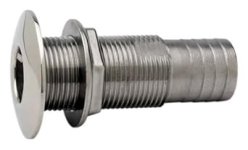
What I wasn't sure about was how I wanted to finish it off cosmetically. I had a few ideas, but hadn't settled on any one. So, I prepped for the option which would also leave all the other ones open, and I left a short bit of tube protruding on either side of the transom, then bullnosed those ends and filleted around them, thinking I might gelcoat it. As I did other jobs, I kept the drain in the back of my mind. One day at a marine store I found a brand/style of through hull that had a nice, low/rounded flange which piqued my interest because finishing off with a through hull was one of my ideas, but I didn't want a really chunky/vertical look. This was just one, wrongly sized through hull on dusty shelf, but it gave me something to go on. Turned out it was an Attwood made of 316 stainless. I was able to source a pair of the right size (3/4") on Amazon (was no longer anywhere near the marine store). They look like this:

41hOWz7qd3L._SX342_.jpg

For my "real" through hulls, I like the Grocos, but they don't have quite as svelte a look.

Once I had the through hulls in hand, I test fit them in a scrap piece of the fiberglass tubing I had bonded in to the transom. As I had figured, they were a bit too large to fit; but nothing that grinding off a bit of the threads would not fix (I was not going to be using the threads anyway). Once I had the diameter just right for a snug fit, I then cut the length of the two through hulls so that they would just meet in the center of the transom. In addition, I took a scoch off the back side of the flange of the lower bit of the inside one, so that it would fit perfectly snugly against the splashwell (which starts to curve slightly there). This is not visible once installed.

Now I was sure it would all work and fit well, so I taped off the transom and used a Fein Multimaster to cut the fiberglass tubing off flush with the inside and outside of the transom. Everything was already bonded in with thickened epoxy, so no gaps or unsealed areas were exposed - while the through hulls will add another layer of sealing, it's completely unnecessary and they were mainly chosen for aesthetic purposes (I could also have left the tube out and just used thickened epoxy and these through hulls, but I'm happy to have both so all is good).

Next I taped off the through hulls (to avoid scratching and/or sealant mess) and the boat (same reason), and solvent washed everything. Then I bonded the through hulls in place with 3M 4000 (decent adhesive properties and supposedly resistant to yellowing with UV - not that much sealant shows in the end). I had pre-made a "puller" out of a long bolt, two fender washers, and nuts, which I fastened in place to pull the through hulls tight and keep them in place while things cured. Later I removed that and the tape and here is how it looks:

Inside:
drain_finished_splahswell.jpg

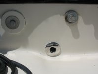
Outside (you can also see a bit of the newly-installed Mini Jacker with the Honda 8 kicker on it):

drain_finished_transom.jpg

Sunbeam
 
ferret30":14zu963t said:
Can this through work with a drain plug, i.e. could this approach work for the bilge drain?

Maybe, but.... probably not very "slickly." Background: Before I did my transom drain (i.e lower sump, not this splashwell one), I considered all kinds of options. Now that's not to say there are not more, but in thinking it over I came up with two scenarios for mine that I thought I would like.

1) Close out the core completely in the way of the drain, and then use a "typical" garboard drain plug type of fitting.

2) Bond in a fiberglass tube and then use the "thermos stopper" type plug in it.

Ultimately I couldn't see any reason I would not prefer option #1, except for being loathe to get started on cutting things out. So I got the tools out and went with #1 (and I'm glad I did; would do it the same way again. I'm glad to just be done with the core there, and plus my sump is now slightly deeper as a bonus). Most of the job is detailed earlier in this thread, although I have yet to finish the sump (i.e. gelcoat or paint) and fasten in the drain plug (it's all fitted, which you can see in the earlier post, but I don't want to "goop" it in place until after I finish the sump).

The reason I rejected the idea of using a through hull and then threading something into it is because most (all?) of them only have the provision to screw the plug in from the "ugly" (threaded ring) side, which to me would be on the inside of the boat -- and I didn't want a drain plug I could only put in from inside. For example, Groco makes a through hull that is threaded both outside and inside, that you can put a plug into (although they specify it for use above the waterline). Perko makes a bronze, "through hull style" garboard drain plug that takes a plastic plug, but it also has the "inside only" issue.

As I mentioned above though, there are a lot of different fittings and it's possible one could come up with something. I liked #1 for the reasons mentioned above, and also because numerous manufacturers make plugs with the same size/fastener spacing, so it would be easy to replace if/when desired.

jd: The lower drain (transom drain) in my boat still looks similar to the way I showed it earlier in the thread (save for an additional coating of neat epoxy). I'll post again when it's finished (which will involve either paint or gelcoat on the sump and caulking/fastening the drain plug in place - although the earlier entry shows it dry fitted).

Sunbeam
 
Follow up to a comment I made earlier in the thread about the lazarette lids.

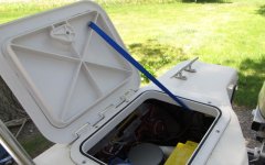
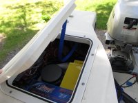
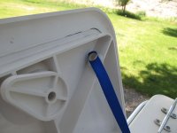
I recently made up and installed some restraint straps for the IMTRA lazarette hatch lids. Without the straps, the lids would open to 180º and (just barely) rest on the deck. I didn't like this from the first time I mocked up the new hatches - because it seems like it would be way too easy to break the lids and because I don't like things resting on the gelcoat - so I figured I'd come up with some restraints.

I wanted the straps to fall into the lazarettes of their own accord when closing the lids (vs. my needing to pull them out of the way each time), and I also wanted them to be out of the "working area" of the opening as much as possible. So, I mocked them up in various ways with some scrap webbing and a couple of pony clamps to figure out where I wanted to put them. Here are the new straps in action. First open:

IMG_0815.jpg

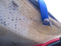
Then closing, showing the webbing falling into the locker. I had thought about encasing a fishing weight into the (tubular) webbing to encourage it, but as it turned out that wasn't necessary.

IMG_0816.jpg

I decided to use snaps to hold the straps on. This way I could remove the straps if I wanted to, and I could also potentially change the length by making up new ones. I sized them so that the lids would open past the "any little breeze will blow them closed on me" point, but not so far that the force on the hinges was great or the temptation to use them as shelves would exist.

On the hatch lid I mounted VHB-backed male snap studs.

IMG_0817.jpg

On the boat side I used screw-in snap studs. This core in this area was previously removed and replaced with thickened epoxy, so I was able to simply drill and attach.

IMG_0814.jpg

Materials and sources:

1) Webbing, 1/2" tubular - REI (outdoor store). They sell it by the foot. Ends were cut with scissors and then melted with a small butane torch/appliance. Holes were made in webbing with a heated awl.

2) Snaps on webbing were in my bosun kit (but are commonly available). I used a "cheapy" snap setting plyer-type tool I own that came from a sewing store (a pro one from Sailrite would be preferable).

3) Snap studs on laz lids are conformable VHB tape backed studs I bought from Sailrite.

4) Snap studs on boat I had "in stock," but are commonly available ones with a "pointy screw" back.

Sunbeam :hot
 
Very nice. If I had installed them that way I would definitely be doing this! I installed mine to swing in so I could access them from the dock or standing on the trailer wheel wells, but I still cringe when I have them half way open and they blow all the way open!
 
Sunbeam,

Nice job on the laz straps. I installed my hatches in the same way as yours, and went through the same anxiety about having them all teh way open (180) so put stops in at ablut the same points as yours, but with an 1/8th inch nylon line. Easily removable or adjustable if needed.

Looks like you are still busy working on the boat. Have a great weekend.

Harvey
SleepyC:moon
 
hardee":c50fq4af said:
Sunbeam,

I ... put stops in ... with an 1/8th inch nylon line. Easily removable or adjustable if needed.

That's a good idea and probably simpler. I can see where you could just make a hole in the support "web" on the lid and then knot the line on one side to hold it in place, and then fasten it underneath in a similar way to the snap stud. I should have thought of that! I guess since I have webbing in my kit, suddenly webbing looks right for every job :mrgreen:

Sure is nice having a "stopper" (of any kind) in place, after worrying about breaking those lids off for months.
 
Back
Top