Webasto Heater Installation

`Seems you're going about your furnace installation smartly, but perhaps for one thing - the high heat outlet. Maybe you've thought of all this and decided the vent behind the pilot seat's right for you. Here's another perspective:

In my 22' Cruiser the furnace is mounted under the galley, the heat ducted through a Y-fitting, one leg of ducting then run to an outlet down by the cabin sole to blow on your feet when at the galley stove or to rise and warm someone sitting across at the table. The other leg of the ducting runs to an outlet adjustable for direction and volume exiting athwartship from under the pilot's feet.

These low outlets mean you're warm from your feet up, not just hips-up ~ a complaint I hear Wallas stove owners express since their heat also enters the cabin at hip-level. The adjustable outlet on our forward duct lets us direct heat up to the V-berth or across to rise around someone sitting in the passenger seat. Cracking open a window a bit helps draw the heat to whichever side.

Shutting off the forward outlet will send more heat out the aft outlet, good for warming the cockpit too when all the 'camper-back' canvas is snapped in.

With the longer ducts secured against bulkheads in the cabinets, they take up little space. I can't take credit for this smart setup: It was this way when I bought the boat from C-Brat Barry Daniel.
 
I thought about installing the heat vent lower, but this just seemed like the best place. I was more concerned with "kicking" the louver off accidently if it was near foot level. I know some have put a vent in the v-berth also, but we like it a little cooler for sleeping. I also use a small fan to "vent" the v-berth, so don't really feel I need to run ducting up there. I figured I would try the vent where I put it for now, realizing I can always add a Y and another vent later if this doesn't work out. Colby
 
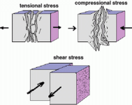
Thanks for the further photos--and not what I had visualized. I would describe the second bracket as "compression supports"--and they should work fine. (As long as they don't bend) You are putting forces mainly in compression for both bolts, with a minimal shear component.

For illustration, and the only simple picture I could easily find is geologic, but the information is the same:

stress.gif

Compression, pushes two pieces together, tension pulls two pieces apart. Shear, the pieces are along side each other, and the force is sliding--one moving the opposite of the other. Your failure was mostly in tension, as you pulled up, with a lever arm.

This illustration is simplistic, and there are many other issues involved in forces, and illustrations of those forces..but this suffices for the glass and and metal. In your screws there are also forces of cleavage. Often forces are a combination, but one will fail first.

Generally epoxy generally has better adhesive properties with fiberglass than with metal. All epoxies are not the same. There are a number of tests showing which epoxy is the better, using testing gear-most tests are done in tension pulling apart, or shear, sliding surfaces. The test results depend on multiple factors, including surface prep, surface composition, moisture, temperature, etc. One of the "Standards" for testing, is "G 10" a fiberglass epoxy laminate.

Your supports between the inside of the two strakes should be strong enough--it is support of the outside edge, which now comes in compression, and you avoid the lever arm tension on the upper (original) glue line.

Yes, you have to get down to raw glass--where you begin to see the glass fibers. If there is surface gel coat or paint--then it is more likely to fail.
 
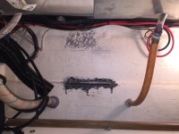
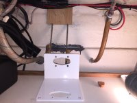
Will Hell! Ok, the bolts are pretty much welded with the epoxy to the hull now. In fact, the 3 I was going to use for the hull side of the mounting plate would probably be all I need to hold that plate. They are not going anywhere. Nor are the two lower bolts that were planned to hold the "compression" brackets. However.... re-studying the installation instructions, reviewing and rethinking the exhaust run, it appears that with this unit, the exhaust should really slope downward. Somewhere in my previous readings I saw where the exhaust tube should be looped to keep water out. Probably the wallas 1300 installation .... Anyway, to get the downward slope in the exhaust tubing, and to keep the exhaust thru hull port at a proper height, I need to mount the heater higher. Trial #3. As you can see from the next few photos, I decided to epoxy some 3/8" plywood to the hull, higher up from where I had previously set those mounting plate bolts. I'm now going to use the side mounting plate that I got from Sure Marine earlier. Again, I did some grinding on the hull. Not completely baring the fiberglass in the entire area of the plywood, but hopefully enough to get enough adhesion to work. I placed 4 bolts thru the plywood first, that will hold the side mounting plate. I will use 2 of the 3 bolts I set earlier now to mount "compression" brackets to hold the outside of the mounting plate. The bottom 2 bolts I epoxied to the hull are there for the duration, or until I decide to grind them out.... :roll:

15_G.jpg
16_G.jpg
The clamps are just to brace / hold up the plywood until the epoxy sets. The side bracket is just laying in the view. I will mount "compression" brackets between the 2 new holes I drilled in the bottom outer edge of the mounting bracket, and 2 of the 3 bolts now set with epoxy on the hull strake. The 3rd bolt is not going anywhere unless I cut it off... :roll:
 
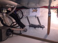
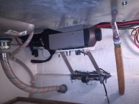
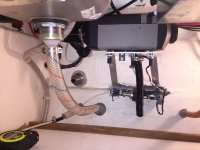
Ok, finally getting somewhere now! :-) All that's left is installing the exhaust thru-hull port, exhaust pipe, and fuel tank, line and fittings. I believe the heater should be high enough to allow me to put the exhaust port either somewhat level with, or just a bit higher than the sink and stove drains, or one step above. These photos are of the mounting bracket, and then with the heater on the bracket.

17_G.jpg

18_G.jpg
(Fuel pump is temporarily mounted on the center bolt between the two support brackets.)
 
If you have trouble with epox use 3m stuff I have used 5200 and it will flex some and is very strong a friend used it to mount the block for his crab pot puller worked great , I put some hangers up in the cabin and had to change it took me over a hour to to get the thing off had to use a chisel and cut it of and it was not easy. Great stuff.
Richard
 
I thought about that Richard, as I've heard it's fairly strong stuff. But I had some Loctite Marine Epoxy (and JB Weld) lying around, so just used that stuff up. I really don't think this thing is coming down. :-) Colby
 
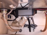
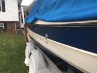
Yeah Baby, cooking with gas now! :mrgreen: Ok, I've always cooked with gas, but now I'm heating with it too. lol. Everything is in, except for the fuel tank. Still waiting for that shipment to get here. But hooked the fuel line up to a small container of diesel fuel to try the heater out. I think we are going to be very happy with this installation! From the photos below, you can see the final installation of the heater, and then of the Exhaust port on the outside.

19_G.jpg

20_G.jpg
The black tube connected to the bottom of the heater is the combustion intake line. I just put that on to bring the air intake down a little lower in the cabinet, away from the heater.


22_G.jpg
Because the Exhaust port is on the widest part of the beam, and sticks out ever so slightly, I will have to be cognizant/careful of that when starboard docking or rafting.
 
colbysmith":2exkrplt said:
Because the Exhaust port is on the widest part of the beam, and sticks out ever so slightly, I will have to be cognizant/careful of that when starboard docking or rafting.

And also that the heat can melt dock lines, fenders, and the hull of whoever rafts next to you.

Mark
 
If the exhaust is that hot, I'd be concerned about the rub strip right above it. My rub strip has sealant along the top and bottom. Heat that melts fenders or docklines would probably damage the sealing of the rub strip too and/or warp the rubber strip or cause the metal to buckle.
 
I don't think it's that hot. :-) My exhaust tubing is about 15" long. While it's blowing like a son of a gun out today, and the temperature is in the 40's, I was able to hold my hand in front of the exhaust port without burning it. But I'm sure on a warmer day, and if something was right up against the port, it could be hot enough to cause some damage. (I'm sure the metal of the port would get very hot.) I'm not so worried about causing that kind of damage (as I know to make sure when I turn it on that I'm not up against anything and my fender isn't hanging there), but I tend to dock on my starboard side and with many docks that have bumper strips, I do not use my fenders. (This is during short tie ups, or at the ramp). That is something I will need to change now, as the port sticks out about a 1/4", and could easily catch on anything sticking off the dock. For that reason, I may consider putting some bumper strips in front of and behind that port, on my hull. Colby

23_G.jpg
 
Looks as though things came together well. I don't know if you are aware, but there are metal (SS) straps like zip ties, which are made specifically for exhaust lagging. You might want to consider those, rather than plastic zip ties.

Even the 45,000 BTU heater I had on my Cal 46 did not have exhaust which felt all that hot. But certainly, be careful of any fenders, etc. I don't think that you will have any problems with the rub rail. It will not be that hot, since the exhaust is forced out--more than up.
 
Hi Bob. Thanks. I think the zip ties will be fine. They are just very loosely holding the insulating sock around the exhaust pipe. I ended up cutting it a little too short, and had to add a little around by where the pipe comes off the heater. If that sock gets hot enuf to melt the zip ties, that will be the least of my problems! :wink: Colby
 
Got the fuel tank yesterday and finished installing that today. Forgot to take some photo's, so I'll try to remember tomorrow and get them uploaded. Very happy with the installation. I've run the heater a few times the past two days, and it does a great job of heating the cabin and keeping it toasty. I'm just sticking with the Rheostat, rather than purchasing the more expensive thermostat system. And while the exhaust coming out the port is very hot at the tip of the port, once you get several inches away (3 or 4) it begins to dissipate. (Just like any other recreational vehicle furnace.) Colby
 
25_G.jpg
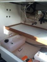
Final installation. A bungie cord will go between the two eyehooks to secure the fuel tank.

24_G.jpg
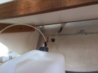
Close up of tank so you can see cap with pickup and vent lines.
 
Brooksjudy could you post pictures of your installation too. I've been thinking about doing the same. Will the exhaust mate to an unused Wallas exhaust thru the hull? This is a great post. I learned a great deal. Thanks to all. Rob
 
Resurrecting this thread, as I'm thinking about changing my current Webasto setup to draw outside air for the combustion chamber. My though process being that as it is now, with the combustion air just being drawn from under the sink where my Webasto is located, is also bringing that outside cooler air into the boat. And quite frankly, I'm not convinced that on a humid, foggy or rainy day, that doing this helps to dry condensation up inside the boat. On the 25 now, with the under sink area open to the bilge by the open space between the head and the hull, it's likely bringing air in through the bilge, but with any windows cracked open, it's also bringing air in thru them. So anyway, are there others with the small diesel fed heaters using outside air for combustion, and how are you getting it? I'm thinking about adding a through hull, just like the ones that are used with bilge pumps, and then placing a clam shell over it to help protect from rain or spray intrusion. I may be able to place this just above the gunnel walk way along the outside of the boat.
 
The blower will bring air from the path of least resistance. I suspect it will still bring in air from the "bilge"--behind the head-thru the area where the cables and wires run, as well as any thru hull--maybe little through a thru hull. If you want outside air, then put a bilge intake, and put it near the intake of the heater blower.

Some heaters bring the air for combustion in around the exhaust port. Air for combustion is different than ventilation. It will be blown out of the boat in the exhaust. Most heaters recirculate the available air in the boat. If it is heated enough, this air is dried out.
 
Hi Bob. Not sure you understood me. I’m speaking only of combustion air intake. I currently have a combustion air intake hose just hanging under the webasto. My tentative plans would be to connect the open end of that hose to a through hull close to the heater. I’m just wondering if others have done something like that or if most are just leaving the webasto or similar heaters draw combustion air from inside the boat. My ventilation air intake is just at the back of my webasto and there are vents in the cupboard doors to allow cabin air to circulate. The ventilation air is routed thru its ducting and vent to the front of the sink cabinet.
 
You should consider that the combustion air inlet is about 1/4 the diameter of the ventilation air inlet. Assuming that the air velocities are the same, the combustion air is a fraction of the total air flow. I'm not sure that using an external source for the combustion air will make that much difference. All the Wallis installations on C-Dorys use the cabin air for combustion.
 
Back
Top