"New" C-Dory Project

Looking at your and your dad's photos, this is the VHF antenna, on the aft starboard outer side of the cabin top. Only a few put the VHF antenna aft here (mostly in concert with a pipe frame radar arch). The longer (8') antenna shown in the photos, is good for a little longer range (about a mile) over some of the other options. The 8' antenna will have a higher "gain" My experience is that my signal is heard and I receive as well as folks with the 8 foot antennas, so the difference in practice is minima...

I prefer the 36" SS whip with a loaded base, on a 25" 1" SS Tubing, which can be folded down to be parallel to the cabin roof. Well meaning and poorly informed people trying to be helpful often grab white fiberglass antennas. The result is breakage. Also the 8' antenna folded down will be longer than the roof of the C Glory 22, and stick into the cockpit or forward of the cabin house.

I have one of the antennas described above on each side of my boat--and just have a re-inforcement sewn over the antenna mount (covered with antenna attached and folded down aft).

How was the antenna coaxial cable led into the boat? Generally these are fixed to the antenna, and cannot be removed. (A few will have a PL 259 connector right at the antenna, but then that means putting a mating barrel connector or a female SO 239 connector.

So I would remove this ratchet mount--you may be able to use it again forward, and ask for a re-inforcement (several extra layers of fabric sewn inside of the cover) over the area where you will eventually put the antenna. The antenna must be at least 3 feet long, but I prefer it not be any longer than necessary, because there is some feed line gain loss.
 
I was obviously in too tight to give you proper perspective of where the mount was located... but this is actually the forward port mount. The aft starboard mount is the one that has been removed and patched.

If the aft starboard mount used to be VHF... it appears that he intended to use this one for VHF moving forward.

As you suggest, the coax appears to be permanently connected to the base of the antenna and he fed the coax (all... what appears to be 25 or maybe even 50 feet of it...) through a hole in the vertical dogleg of the cabin roof outboard and below the mount that you see. Any advantage he had with the 8 ft antenna was lost in the long run of coax. Obviously, dad was not a ham and did not consult his ham son on this one. The distance from the base of this mount to where he mounts the radio is maybe 3 feet, max.

Your antenna setup sounds interesting - are you intentionally using the lower SS tube as a counterpoise? It sounds like you essentially have a vertical dipole, or something close. Was the 25" a length specifically chosen for the frequency, or just happened to be the size you used? If you have two antennas, is the other for 2m or something... or redundant for marine VHF? How are you connecting the whip to the tubing? Does the coax run up through the inside of the tubing?
 
These approximately 36" (Are adjustable and the 36" is generically used although they are slightly longer) whips are base loaded--no counter poise needed. The base extensions are sized in 12", 24", on up to 48 or more on custom order. (I should have put 24"...

The 1/2 wave of channel 16 on Marine VHF is 37.65 inches. I have not recently checked the tuning of my current antennas, but in the past found the whips pretty close to half wave at channel 16.. (The band runs from 156 MHz to slightly over 162 MHz. Generally tune for the 156.800 which is channel 16. Most of the commonly used channels are close to the 156.8, with the higher end being receive in the duplex channel, and the AIS signals (and the reason for best AIS to have a separate antenna).

Actually the loss in the coax depends on which coax it is, but the 8 DB gain is more than the loss. Since you are a ham, you know that as the gain increases the pattern horizontally narrows. Thus the heeling or rolling effect becomes more important--but this is mostly in sail boats.

The older photos of the boat showed what appeared to be a Loran C antenna in the center of the boat, with a coupler at its base--and so I made a false assumption... I can see when the VHF antenna was aft, that the cable went further aft, and probably entered at some point under the lip of the top.

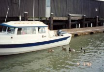
JustDucky.jpg

Where you want to place the antenna depends on what other instruments you may want to use. Radar seems to have been ruled out--and that is what traditionally would go in the center.

You can just remove the upper part at the ratchet point and bolt. Then have a re-enforcement or small pocket sewn over this...if you want--or completely remove the mount, and fill the holes. There is much more tension on the cover for a device in the center (if this is in the center) than one off to the sides, where the fabric has gone over the hand rail, and is then going over the lip of the cabin top.
 
thataway":2l4gm5au said:
Actually the loss in the coax depends on which coax it is, but the 8 DB gain is more than the loss. Since you are a ham, you know that as the gain increases the pattern horizontally narrows. Thus the heeling or rolling effect becomes more important--but this is mostly in sail boats.

Correct. There isn't any marking on the coax so I don't know what it is - but it does seem like pretty lightweight stuff. You're right that the loss won't completely offset the 8db gain, but it just seems wasteful to have that much coax when it's not needed. I'm not convinced the VHF is a true "gain" type antenna (like collinear), but I'll investigate more when I get to that.

thataway":2l4gm5au said:
The older photos of the boat showed what appeared to be a Loran C antenna in the center of the boat, with a coupler at its base--and so I made a false assumption... I can see when the VHF antenna was aft, that the cable went further aft, and probably entered at some point under the lip of the top.

You are correct - it is the Loran forward and VHF aft in that picture. The Loran is offset more than it appears, though. The masthead light is centerline, the Loran is not. Here's a shot I took from an upstairs window that does a better job of showing the offset of the forward mount - the aft mount was similarly offset to starboard (probably can't see it in the picture, but up close I can see where the roof was patched. He takes the hand rails off for storage.

offset.jpg


thataway":2l4gm5au said:
You can just remove the upper part at the ratchet point and bolt. Then have a re-enforcement or small pocket sewn over this.

Sounds like a plan. I'll be calling in the cover order tomorrow.
 
Back
Top