Here are the photos:
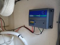
Battery charger:
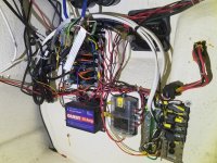
 Wiring behind console:

I don't see anything specifically wrong with the mounting of the battery charger, except I like to run the boat wiring which has the white vinyl sheath on the outside. The red and black wires should go directly to the batteries. This Guest charger is a 5/5; that is 5 amps to each of two batteries. There is only the output for one battery.
As I go to the photos of the console--I begin to see issues. The photos sent to me were a high resolution, so I can see more there than when compressed to put on this site. The AC panel is a Blue Seas 8027--standard AC main breaker, so both the neutral and hot should be switched on and off...This panel is in the right lower corner of the photo.
Problem: The neutral is wired directly to the neutral bus bas, and is not switched on and off--it should go to the first breaker (white wires). Thus, it leaves the neutral on all of the time--and if the boat or power pedestal has the hot and neutral reversed--more common than you might think-- this leaves the neutral hot;
Problem:: The panel is probably after build installed. The cutout isn not smooth. But more importantly there is
no cover over this whole panel. The hot (black) is exposed--and it would be easy for anyone to touch this and be shocked--or worse--if a metallic object were to fall across this--it could short and cause a fire.
There is a galvanic isolator--we hope properly wired.
I cannot trace the battery charger output from the photos, but on examination closely the same type and size of wire goes to the common positive bus bar (Red) and to the common negative bus bar (black), instead of one set of leads to each battery! At least it seems to be fused.
There must be at least one more outlet: There are 3 110 V wires groups (green, white and black) to the panel--one is the in--10 gauge, and two out 12 or 14 gauge. wire. One must go to the battery charger, and one must go to an outlet somewhere in the boat. You have to turn the panel breaker (hopefully labeled battery charger) on to have the charger work.
Solutions: Immediately get a cover for the back of the 110 V AC panel--to prevent anyone or thing from touching it.
Move the white # 10 wire from the common bus, to the input of the first circuit breaker on the 8027 panel.
Rewire the battery charger output properly: use at least #12 wire, (red and black or red and yellow) in a vinyl sheath, directly from the battery charger to each of the batteries. There may be a common negative for the batteries. Be sure that it is fused at both ends.
Remove the wires from the battery charger to the terminals under the console. Label all of the new wires, at origin and terminus. I like to use crimp fittings with adhesive shrink tubing. If you don't have a good ratchet crimper--buy one now.
Find where the 110 V shore power connector is (on side of cabin, or perhaps under the gunnel in the aft bulkhead)--it will be where that # 10 triplex wire terminates which goes from the 8027 panel. It looks to me viewing the battery charger photo, that this wire goes thru the aft bulkhead. There should be a rubber grommet where it passes thru the tabbing. If you don't have a shore power connector/cable--go with the "Smart plug" or equivalent. You should theoretically have a 10 gauge shore power cord.
I am happy to walk you thru each of the steps via e-mail or phone call if you need assistance.
When you find the inlet plug, send me another photo, and I'll post it for you.
Thanks!


