Calling all VHF specialists!

C-Val

Member
Hi Everyone

On my Christmas break I have been trying to sort out a VHF voltage drop.
I am using a standard horizon 1700 about 3 yrs old.

I had it on one boat with a 8' Galaxy Shakespeare -- it worked great. I moved it to another boat with a brand new 8 ft Classic Shakespeare (with a recently soldered pl 259 by me a newbie). Even connected directly to the battery I am getting a massive voltage drop (from 12.5 to 7 volts) with PTT. I changed batteries and still the massive drop

When I put it back to the first boat my voltage drop is so small (maybe .2)
Back to the new antenna connected directly to battery again and massive voltage drop. I tried an old radio I had on hand with the same results.
The only thing common is my new antenna

I checked the soldered end of new antenna for resistance between the outer jacket and center pin. It read "1" which I assume is no resistance.

Is there any way at all that a poorly soldered pl 259 could cause this?
If so I might have to go try a crimped. I watch Dr Bobs pics and tried to follow best I could- may it is not good enough

If you have any suggestions I am all ears. I am at a loss right now. I thought voltage drops could only occur from poor power feeds - not when connected to a good battery directly

thank you

David and Val
 
It sounds like you have tried to rule this out but the symptom you describe is usually related to the 12v wiring. When you say "connected directly to the battery" I envision the radio sitting on top of or next to the battery with no switches or fuses between, and relatively short wires. But if what you really mean is that the radio is connected directly to the battery terminals instead of being connected to a switch or fuse panel, then you can still have a wiring issue somewhere between the radio and battery. Usually it's traced to a faulty inline fuse or fuse holder. Doesn't take much corrosion in these to make things start acting wonky. Is the inline fuse holder the same on both boats you are testing?

-Mike
 
MikeR":3i7ota57 said:
Usually it's traced to a faulty inline fuse or fuse holder.

David & Val, I see your boats are of the 80's vintage. The older glass fuses were a nightmare, especially in boats. My 82 Campion still had the glass ones. Often the inline fuse holders still used them after boats and cars transitioned to the plastic encased fuses.

I would recommend anyone with an older boat upgrade their glass fuses to breakers or plastic fuses.

A poor ground connection is a common source of voltage drop. Just a couple of thoughts - maybe not your current problem.

Regards,

Rob
 
Just want to confirm that you are talking (or reading), Volts DC, and not amps because the draw to go from standby(or listen) is .45 to 1.0 amps and to transmit it goes up to 5.0 to transmit it goes up to 1.0 or 5.0 depending on low or high transmit power.

I have watched my volt meter when going from transmit to receive and I'm sure it does not drop 5 volts, maybe 1/2 volt for the tx time and then back up to 12.8 or so.

I tend to agree that it may be either a wire corrosion factor or an undersized wire for the length of run. When you say it is connected directly to the battery, by how long a wire?

Oh, and I am not a VHF expert, but I have some experience using them and am a firm believer in having at least 2 working radios on board all the time.

Harvey
SleepyC :moon

January_2010_346.thumb.jpg
 
I will do my test again today on my last day off, but just to clarify I carried the battery up to the helm and clamped the 12” wires that come out of the radio to the battery posts

There is a glass inline fuse that came with the radio there however

The weird thing is when I put the same radio back in the original boat on a different antenna I only get a .2 volt drop

I was just wondering if my first time solder job on the new antenna could be the source of voltage drop

Thanks for helping me think thru this

I will repeat my test today to confirm
 
If that first time solder job shorts out the ground and the positive side on that antenna, it will burn out the transmitter finals on the radio. When you put an ohm meter across the plug on the antenna, you should see the "zero" resistance or open. There should not be any connection between that shield and the core.

Harvey
SleepyC :moon

JC_Lately_SleepyC_Flat_Blue_070.thumb.jpg
 
There is a protection circuit in the output finals of the transistors in the radio, which will protect the circuit--and final output transistors. It is very possible that a dead sort in either the PL 259, the coax or antenna, will cause the shutdown--normally this does not act as a short--but it is possible that it does in this case. Thus dropping the voltage severely. This would normally blow the fuse--so you do need to re-evaluate that. I usually pull the fuse out of the circuit--and use one on the fuse block--see below.

I would try with an "emergency antenna, or other antenna, before going any further.

All of the other comments are good and very valid suggestions, and where you have both looked and pretty well ruled out by putting the radio directly on the battery.

Also I find that most C Dory's do not have adequate wiring from the batteries to helm--and I either double the wiring--(add an extra #10 or #8 wire for the positive and ground to the electronics section. (I also often another or large fuse block--go from 6 to 12 fuses).
 
Almost certain this is a problem with the DC wiring...a corroded connection, corroded fuse holder, too small a diameter wire for the length of the run, etc. I occasionally do radiotelephone safety inspections for commercial vessels and this is not at all unusual in an older installation. If you did a lousy job soldering the antenna connector, as others have noted, the radio would likely roll back power so that it did not damage the output circuitry. In that case, since the radio would not be transmitting at high power, there would be little current draw increase over receive and hence no real voltage drop. So, I agree with those that say the issue is likely with the DC wiring. I'm not saying there isn't another problem, or that the antenna connector is not an issue, but I would start with a look at the DC wiring.

Gerhard
PS. I've chased my tail for hours on one of these, so don't give up!
 
checked the soldered end of new antenna for resistance between the outer jacket and center pin. It read "1" which I assume is no resistance.

The "1" with an omega should mean one Ohm, 1 with k Omega sign is 1000 Ohms, and 1 with a m omega sign means 1,000,000 Ohms. Many of the VHF antennas will read one to 2 Ohms--the design and type of the antenna are variable, and "resistance" read across the center conductor to the braid (ground) does not indicate a short necessarily. A dead short would be the same as connecting the leads together and would read near 00 Ohms.

As for power consumption: a 25 Watt Marine VHF will draw about 5 to 7 amps at full power on transmit. (about half an amp on standby/receive) Normally that load would not cause much if any drop in an adequately wired circuit.
 
Frankly, I'm a bit puzzled by your description of the problem; that is, a "voltage drop". Voltage drop is usually measured in a static situation (i.e., when no load current is flowing). If the VHF is turned on, then like all loads, the entire voltage potential "drops" across the load. A partial drop in a live circuit doesn't mean anything unless there are multiple loads in series and you are measuring btwn the loads.

Where exactly are you measuring this "voltage drop" and is the radio turned on or off when you measure it.

P.S. If you are measuring across the battery terminals with load current flowing and see a voltage drop, that has to do with the internal resistance of the battery not with the load.
 
P.S. If you are measuring across the battery terminals with load current flowing and see a voltage drop, that has to do with the internal resistance of the battery not with the load.

Good point--but he had said he "changed batteries"--which should rule out the bad battery scenario. If he is measuring past the fuse--that much drop should have blown the fuse--but we don't. know how much current he is pulling--and measuring that would be a step to take now.

My assumption was that he was measuring the voltage of 12.5 volts before he hit the PTT button, and then 7 volts when hit the PPT button. Although 12.5 is a slightly lower than the resting voltage of a fully charged battery, often long, undersized wires, corrosion, and poor connections, will cause a small voltage drop.
 
Hi Everyone
Thank you for all you insights into my vhf voltage drop problem

Just to clarify, I have a fully charged spare battery I brought up to the helm.
I dismounted the SH 1700 and set it virtually on top of the battery with the short wires from radio connected directly to battery posts. (there is an inline fuse on power) Voltage is measured right from battery posts.

I have access to two boats. When I do this on the first boat connected to its antenna voltage drops only about .3 volts when I key the mic. (This is a Galaxy 5225-xp higher quality antenna)

When I carry the radio and battery to the second boat with a new 5101 Shakespeare entry level antenna (with my solder job), voltage drops from 12.5 down to about 7 volts when I key the mic on 25 watt.

According to the shakespeare antenna manual there should be no continuity between the centre pin and the outer ring. When I checked my 5101 antenna there was no continuity so I assumed I did good job.

After much research and reading your posts, my only conclusion is something I read on another boating website. It states

"If there is a bad connection in the coax or the antenna, too much power is reflected back to the radio and the radio itself will begin to power itself down to protect itself"

I wish I had a vswr meter but I don't. I contacted the local ham radio club here and they invited me to attend their meeting tomorrow. I will let you know how it goes.

I think they want me to join the club and get my ham radio license for marine!

This has all been a bit discouraging for me as I wanted to use the boat over Christmas. The upside is I will pretty soon be a radio tech myself!

thanks again

David
 
David, it seems to me that if the antenna is making the difference, the antenna is the problem! (Or the antenna's connection to the radio.) Or am I missing something more in your posts? It could be a bad antenna or a bad connection. The easiest thing to do would be go to Radio Shack and buy a new connector, one that is solderless. Install it and see if the problem is solved. It could also be in the antenna cable as well. But again, the easiest thing to start out with would be remove and replace that connector. (Actually, check your cable first to make sure it's not pinched anywhere, and is connected properly at the antenna.) Colby
 
I'd like to correct one thing I said above.

"Voltage drop is usually measured in a static situation (i.e., when no load current is flowing)."

As stated, this is wrong. I chose the words poorly. Voltage everywhere in a circuit is the same if no current is flowing. Voltage drops occur when a current flows thru a resistance; so having a current flow is necessary for a voltage drop to occur. What I meant to say is that if you are measuring a voltage drop when no load current is flowing (i.e., the load is turned off), and you measure a voltage less than what you measure at the source, then there is high resistance somewhere btwn you and the source (e.g., corroded junctions, too long a run with too small a diameter of wire, etc).

I regret the use of the word "static" because there really is no such thing. In order to measure the voltage, you need some sort of voltmeter. All voltmeters draw a tiny amount of current across a high resistance....that's how it measures the voltage via the V = IR law, where I is the amps flowing thru the meter, R is the resistance inside the meter circuit, and the calculated V is the voltage the meter is calibrated to report. So when you measure the voltage btwn 2 points in a circuit that is "turned off", a tiny amount of current is flowing in that circuit assuming there is a source connected. Note that a voltmeter doesn't really measure voltage, but rather it measures this tiny current passing thru the meter.

Another way to say this is that while you are measuring the voltage in a circuit where all loads are turned off, there is still one load that is on....namely, the voltmeter itself.
 
David & Val,
I think you have already diagnosed the problem and don't realize it is in the antenna. 100% of the reflected power is going to be returned to the radio if a short occurs in any part of the feed-line. And as Bob has already stated, the radio's circuit has prevented damage to the final transistors by shutting down.
 
One thing that I have not yet seen mentioned. When checking your antenna, you should check it 3 ways. The OP has checked one. That is make sure that the circuit is not closed (or is open) between the tip and collar of the PL 259 connector.

The next one is to check the tip of the connector with the antenna (or antenna inner connection at the mast) This circuit should be closed with very little resistance.

The third test is to check the grounded side of the antenna with the collar at the PL259 connector. Like the tip, it should also be closed (have good continuity) with very little resistance.

Upon further review, Barry did touch on it w/ the shorts. My explanation is how to find the shorts.

Abnormality in any of these 3 can cause many headaches.
 
I met the ham radio club today.
They were very interested and helpful
They looked at my solder job and said it didn’t look that bad
(Thanks for the illustrative pics Dr Bob!)

Tomorrow they are doing a field test on my antenna

Will let you know how it goes
David
 
Hi Everyone

The Ham radio club confirmed today what many of you already suspected - my brand new 5101 vhf shakespeare antenna is shorting out inside drawing too many amps and causing the voltage to crash. They confirmed my solder job was not the problem (yeah!) Both my old radio that came with the boat and my newer Standard Horizon 1700 transmit perfectly with virtually no voltage drop.

Now I have to apply for my Shakespeare warranty! (good luck to me)

What did get me by suprize is they also ask to test my "good" antenna which is a Shakespeare but higher quality (5225 xp) The swr reading was almost 4! (tech sheet says 1.5:1 but Ham club says 2 is acceptable)
They said it also has to go back for warranty!

Then they put a good quality antenna they had on and reception was a clear as a bell. My "good " one was working but not at the level is was advertised at.

Lessons learned for new year:
1 Everyone should know someone with a vhf swr meter
2 Don't trust new antennas. Check their output before you mount it.
3 Annual checks should be made on these antennas to make sure they are working at their designed level.(After all vhf is one of our primary life saving devices when out on the water) My "good" one was under transmitting for who knows how long and I did not know it. My radio checks were still readable.
4 Give a thumbs up to you local Ham radio clubs - they are there to help
5 Belong to the C Brat Boat club and never stop telling them how grateful you are for their wisdom and patience and we walk thru these issues together.

HAPPY NEW YEAR TO ALL !

David and Val
White Rock BC (with the still broken pier!)
 
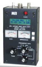
I am happy to learn that our issue was resolved--and that the local ham club helped. If I am buying a fiberglass antenna, I take my antenna analyzer with me to the store, and test an antenna, until I get a low SWR.

The below is comparable to the older model I have (mine uses a separate very accurate frequency counter)

MFJ makes a boat load of ham related gear. The average C Dory owner would not buy this type of meter, but the serious ham should have it.

ZMF-259C-0005.jpg


There is a cheaper MFJ-208 for about $100 for VHF only. There is no frequency counter.
 
Back
Top