Here are a few photos, CDory23. It somewhat pains me to post these right now, as I have many wire ties and supports removed, which means wires dangling, and just a basic overall untidy mess (ugh!). I'm in the middle of making a few improvements, so "pardon the construction debris." Also, as Thataway noted, my system may not be one you want to emulate. You may prefer a "runabout" type system.
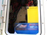
This photo shows the overall layout of the batteries. The blue battery is the house bank, a Group 31 AGM. The yellow is the start bank, and I'm not actually sure what "group" it is but it is a Full River HC44 AGM. It's a little smaller than a Group 24 in physical size, but larger than a U-1. Has 560 CCA.
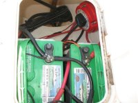
For comparison, here is how it looked when I got the boat. The setup was a "runabout style" system with two flooded-cell Group 24 batteries and a 1-2-Both-All switch (and precious little else). Many things attached right to the battery posts (no buses), no labels, little secured, etc.. Also the original (leaky) lazarette hatches.
Back to now, these are the cleats made of fiberglass angle. They are secured with tapped machine screws that go into thickened epoxy plugs in the cored lazarette bottom. There are Weld Mount footman loops attached to them that hold battery straps. When the angles are removed, the locker bottom is completely flush so that I can slide the batteries in and out. There is some cork and gasket material between the angles and the battery case for padding.
The circle of epoxy you see is one of the original battery tray holes that went into the core, now plugged.
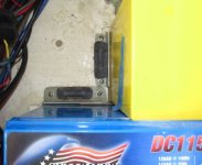
On the side where I don't have a strap, there is a Starboard cleat, also fastened with tapped machine screws.
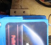
And on the end opposite that the locker wall is angled, and the battery didn't want to sit quite right. There I made a stainless "angle" (around 4" x 4") with a starboard piece attached to it where it contacts the battery (you can't see that part though with the battery in place). This photo shows the bottom of the angle, from the view you would have if you were lying on the sole looking straight up at the bottom of the lazarette shelf.
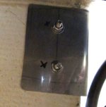
Next photo shows a Weld Mount footman loop adhered to lazarette side. These hold the top end of the battery straps.
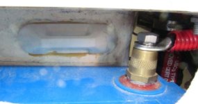
Moving around clockwise starting with the hull side just aft of the starboard fuel fill (in the lazarette). Negative bus.

Positive bus (this is between the house battery and the switch, electrically, and has loads I want to be constantly "live," such as bilge pumps and battery monitor.
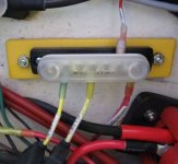
Then is the switch although I don't have a photo of it right now (is apart while I make a few mods).
Next, still on hull side is the shunt for the battery monitor. Electrically this is between the house battery negative and the loads (negative bus).
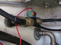
Next, looking straight aft you can see the bilge pump discharge hose, the trim tab relay, and the edge of the ACR, which is on the inside "wall" of the lazarette. Ugh, look at those wires/cables! It's going to be nice to have them cleaned up again.
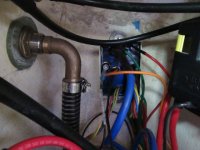
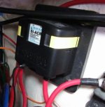
ACR. After this is the Safety Hub (has main fuses) and then you are back to the yellow start battery.
I will still need to find a home for the windlass breaker, plus autopilot pump (future). I also may move the house bank out of the lazarette (and add a second battery), but again that is future, because as it stands now I don't have a practical way to re-charge "more battery" than I have now. I'm already at around 5x the size of the engine's alternator.


