120v Inverter/Shore Power switch or relay?

CharlieRock

New member
Looking for electrical, safety or power efficiency insights on 120v wiring. I just upgraded our Inverter to a 2000w PSW Renogy. I replaced the Wallas stove with an Induction stove, and am adding a Microwave under the Forward dinette seat and a portable Fridge under the table. I just wired in a 120v outlet (lots of bad words getting the heavy gauge wires under the flooring to follow the path of the water lines from tank to sink). Under the galley I have 2 outlets, one for the inverter and one for Shore Power (there is probably an efficiency to combine them). Looking for recommendations on a switch, relay, converter or recommended device, so that the dinette outlet, can be connected to the inverter (primarily microwave or MacBook power), or Shore Power (for the Portable fridge when at the dock.
 
You will want to use a manual transfer switch. A single circuit 15amp is all you need. I have a Hubbell GENSWITCH515 wired into my house for power outages and if I remember correctly it was less than $100 CAD. It will isolate the two power sources so that you cannot accidentally run both shore power and inverter power at the same time.
 
I would use an automatic transfer switch: Here is an example. Magnum is well thought of in the inverter world.

A 30 amp auto transfer switch is here

A few other thoughts: What batteries are you going to use and where are they going to be located? Be sure that the water heater and battery charger are not on the auto transfer switch current. If you are going to run both the inverter and microwave, at the same time, then you will want a 30 amp transfer switch.

You will want at least 100 amp hours usable battery power (either 2 AGM group 31's or one 100 amp LiFePO4 battery, and a way to rapidly recharge the batteries). You will need heavy cables--at least 1/0 up to 4/9 battery cables from the batteries to the inverter.

Then you will have to rewire the 110V plugs that are going to run the induction burner, microwave and refrigerator so they are all going thru the inverter. All of the 110 wiring, should be 12 gauge Marine stranded wire, not romex solid wire as used in household wiring.

I have done this on two boats. There are two ways to do it. The Tom Cat, I just put in split 110 V 15 amp outlets, so that when I was on inverter power, I used one side of the 110 V outlet, and mains power the other side. this gets away from completely re-wirng the boat. On my current 25 C Dory, I am using a 2000 Watt PSW Victron Inverter/80 amp charger/50 amp power booster, which has a built in transfer switch. (Much easier to use an inverter with built in transfer switch.)

In the latter case, I too power from the main 110 V panel, off the "outlets" and ran it to the inverter. then I ran the wire back to the main panel, where the inverter is now hooked up to all ov my 110 V outlets (except the air conditioner, Battery charger and water heater are all on separate 110 V circuits from the main power panel.

The Tom Cat I put in 2 AGM group 31 batteries about 2 feet from the inverter. The C Dory 25, I have 2 Battle Born, 100 amp hour LiFePO4 batteries. I found that I needed ore than 100 amps usable. I also run 12 volt refrigeration (two top loading chests; one a freezer and the other a refirgerator.).

Your way is very similar to what I did with the Tom Cat. I am not a fan of a the output from an inverter being thru a 110 V duplex outlet. Hard wiring is safer, and I believe to ABYC standards for permeant installation.

For the computer, you are probably better using a small inverter-such as 150 watts. The MacBook only draws about 60 to 85watts depending on model.

The microwave will probably pull 1000 watts. (I know that some microwaves are labeled "700 watts", but that is output, not input. If you don't already own a Kill-A-Watt meter buy one. It will show the power draw of any appliance, in watts, amps and cumulative over time watts, plus voltage and hz (cycles).

You also want a shunt type meter for current draw to the inverter. The Victon 702 or 712 (blue tooth to I phone, makes it slightly easier to use). I don't know what the charging output of your Yamaha outboards are--but it will need all of the power to recharge the inverter battery bank.

Draw out your circuit before you start running wiring.
 
Great points above. However a 2000 watt inverter only puts out a maximum of 16.6 amps so a 30 amp transfer switch is overkill. It won’t hurt anything but is unnecessary unless you plan to run a larger generator or inverter at some point. 15amp is sufficient.
Those Magnums appears to be at a very good price point!
 
B95054":2iitqcez said:
Great points above. However a 2000 watt inverter only puts out a maximum of 16.6 amps so a 30 amp transfer switch is overkill. It won’t hurt anything but is unnecessary unless you plan to run a larger generator or inverter at some point. 15amp is sufficient.
Those Magnums appears to be at a very good price point!

Most of our boats are wired for 30 amps from the factory--they have water heaters, battery chargers and then circuits which have breakers for 15 amps. So that input power to the boat could be well over 15 amps. So it depends on how you wire the boat. My inverter with will actually hand 50 amps, and will boost surge (synchronizing with mains current) to 50 amps if needed.

You don't want to undersize transfer switches. If you are certain that you nor anyone else will use less than 15 amps--then OK. But it is the appliances which may be used, and how the boat is wired.
 
With all due respect....
Sizing is done according to his inverter and load size and not the shore power size. He is wiring one receptacle into his boat and therefore only needs one circuit of power. His 2000 watt inverter will put out 16.6 amps of constant current (ohms law. 2000w divided by 120 volts). He may add additional outlets on the same circuit but available current is limited by his inverter size.
The 50amp of your Victron requires the presence of shore or generator power to get to 50 amps. It allows for the supplement of battery power for short term additional load requirements when you have maxed out your 30 amp shore power. That is not what the OP is looking for since he is using a 2000w Renogy pure sine wave.
He absolutely should not overload his inverter so to properly wire a 30 amp transfer switch he would only wire one of the two circuits and leave the other circuit unwired.
I stand by my statement that a 30 amp can be used but is overkill however I will add that wiring should only be done to a single circuit only. Or just buy a 15 amp transfer switch as I suggested.
Btw it has not been discussed but there a different camps on the merits of manual vs automatic. Personally I prefer manual as one more method of control for phantom current draw and it does not bother me to flip a switch when I want power but also appreciate the convenience of automatic transfer switches as well.
 
I'm not sure I understand the desired power configuration, but if all that's desired is to run some units/outlets either on shore power or off an inverter at the users discretion, I just finished such a project. I don't know if I did it 100% properly, but I know that I did it simply.

For each desired 120v driven unit/outlet, I simply installed a 120v 15amp DPDT toggle switch (other types of switches could be used too, e.g., rocker). I wired the unit to the center 2 lugs of the DPDT toggle, then shore power (from the panel) to one set of outside lugs, and inverter power to the other set of outside lugs. So I just throw that toggle switch to shore or inverter depending on what source I want to use for that unit/outlet at that time.

The shore and inverter circuits for any unit or outlet are completely separate. There is no interconnect between the 2 power sources at all. That's one reason I used DPDT switches instead of SPDT switches.....I didn't even want to share the neutrals. Note I have no need for a transfer switch since the DPDT toggle switch can only be in the one position or the other (never both). This setup also gives me total flexibility since I can power any unit/outlet from any source independently of how I am powering any other unit/outlet.

Clearly, this setup only makes sense for a small number of units/outlets since I have to run wires from the inverter to all the units/outlets for which I desire dual sources (effectively double wiring). If there are lots of units/outlets, it would make more sense to bring both sources of power to the panel and use the existing wiring (requiring the transfer switch) as has been described in other posts.

P.S. One nit puzzled me in doing this. What to do with the ground wire on the inverter circuits? I finally realized that on a plastic boat not connected to shore power, the ground floats so the inverter ground is not connected anywhere.
 
Oh boy, I am not making any friends here today :D :D
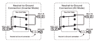
On shore power you are grounded to earth but on inverter power you rely on a bonded ground to neutral. The DPDT switch does not allow for a proper bonded ground to neutral. That is why you need to use a transfer switch. Floating the ground on your own creates a safety risk with no backup fusing which is why it would violate the electrical code and AYBC standards. In other words it could nullify your insurance if it were deemed an incident was caused by incorrect wiring and lack of fusing. In one of the posts above there is a link for a $40 transfer switch. That seems like a pretty low price to not invalidate insurance and create a potentially dangerous situation.
 
What do youall think of this unit?

https://www.renogy.com/3000w-12v-pure-s ... d-display/

There is a 2000w and newer 1000w model as well.

It is an inverter/charger combination with an automatic transfer switch. When AC power goes out, it switches to battery inverter quicker than you can notice. It can also "close" grounding when switching to battery inverter from shore.

I bought one of these originally so that when power went off in my greenhouse, the pellet stove (which heats it) would continue to work, as I could lose all of my veggies overnight or if I am not here.

If the power was off for an extended period, I could hook up my generator and run for a bit while recharging the batteries at 75 amps (65 amps for the 2000w). Worked great so far for several months and several outages. I've also run the batteries down a few times and then used line or generator to recharge to test it. Recharging is fairly quick with the LiFePO4 batteries I use.

So, I got two more at a discount (dented and scratched) for a good price. I had about 3 months to test them, and all worked. I've tested one in my C-Dory 22 with 2 LIFePO4 100amp batteries, and though heavy, it works great so far.

To me, this seems a very flexible system, particularly in the winter PNW (not getting much from solar) when you have a generator or shore power and use a lot of 120 VAC. I run my trolling motors a lot, and this system can nearly keep up when a generator is running.

Any concerns? :clock
 
Not directed to any specific post,

I have concerns with inverters which are not built to marine and ABYC standards.
I am concerned with fusing (DC type T fuse), Terminal and lug size, , and wire size--both for DC, grounding case, type and size of AC wiring. The use of proper switches and terminals.

These inverters use a lot of power. They need temperature sensors for the batteries, they many need forced ventilation (for example fans to remove heat from the area where they are installed), They may need shock mounting.

The concern is safety.
 
B95054":2r6vsx7v said:
The DPDT switch does not allow for a proper bonded ground to neutral.
Could you explain this a bit more?

I probably didn't make myself clear. First, I used 14-3 marine stranded wire cable to do this wiring. All the green ground wires are connected to the outlets (which means the shore power and inverter power greens are interconnected). The black and white wires are switched, but which ever position the switch is in, the situation is exactly the same as if the black and the white were a single piece of wire -- having the switch there would be the same as if I cut each wire and then just twisted the ends back together.

One thing I failed to mention is that if I am plugged into shore power, I never use the inverter. OTOH, while at anchor I sometimes use both the inverter wiring and the standard 120v wiring energized by my generator. In that situation neither the boat nor the generator nor the inverter have any connection to ground; so I couldn't see how my project could harm anything. The one thing I did not do is ground either 120v wiring to the 12v negative. I figured that would be a mistake for sure since then metal surfaces on the boat could be at the potential of the earth (although poorly bonded via the salt water) via a malfunction in the electrical system of the engine .
 
Certainly

There is a big difference with grounding between shore power and when running off of a generator or inverter.
First to explain this properly we have to understand why to ground in the first place. It is there to protect you and your appliances from surges. For the most part an electrical circuit is balanced but when something goes wrong ... like a surge...the is a huge amount of excess electricity and that additional electricity has to go somewhere - hence the ground. We are all guilty of bypassing that third prong on extension cords at some time and everything works. But the ground is there as a safety device and if something goes wrong you risk injury or fire.
So now back to the difference between shore power and locally generated power.
On shore power that ground is wired to a rod that goes into the earth and that excess electricity (if it happens) goes into the ground and disperses.
In the case of a generator or inverter you don’t have the luxury of wiring into a rod driven into the ground so you have to come up with another plan. So what they do is bond the ground to the neutral and the protect it with a circuit breaker or fuse. This means that if a surge happens the excess energy follows the path of the ground and which then trips the breaker or blows the fuse thus dispersing the excess energy. This is what is known as a floating ground.
No ground at all is the equivalent of cutting that third prong off of your extension cord and eliminates all of this security ....but that surge of electricity still has to go somewhere. Electricity always takes the path of least resistance so it either fries up the wires in the appliance or worse yet finds its way into the human that is holding the tool or appliance. That is why you need a purpose built transfer switch which has been designed to incorporate all of the safety features of both the shore power ground or the locally generated powers floating ground.
 
Power surges in your house are a part of life and the equipment being powered has to handle it or be ruined. Power surges have nothing to do with the green wire. Also, my inverter has a transfer switch builtin; check yours.

That green wire is there to ground the chassis, the structure which supports the electrical equipment. It has 2 functions: one is to eliminate the noise on the chassis and the other is to provide a ground path if the power return shorts to ground. The GFCI receptacle does this by comparing the input current (black wire) with the power return (white wire) to to make sure they're the same. It's assumed that the current difference goes through the chassis ground (green wire).

In a house, both the power return and chassis ground are earthed, often at the same place. If you tie them together in a boat and and connect shore power,the dock GFCI will disconnect the power.

I use terminal strips to power my computers. They smooth out the power surges, which are voltage surges. I also ground the chassis on my instruments in order to reduce the stray voltages/currents.

Boris
 
I believe we have some talk of apples and some talk of oranges going on here at the same time....

Grounding is an issue in 2 completely different situations. One is protecting against a surge due almost always to lightning; and the other is providing an Equipment Grounding Conductor (EGC.....this is the "green wire") to protect humans from a ground fault in a circuit. We've mixed up these 2 protective practices in this conversation.

B95054 is correct when he says: "....we have to understand why to ground in the first place. It is there to protect you and your appliances from surges.". But I presume B95054 is talking about a surge created by lightning. Only lightning surges need to be directed to the earth (Note electricity does not "seek the earth", but rather it seeks to return to its source by whatever and all paths it can find with the most amps flowing in the paths with proportionally lesser resistance.) In the case of lightning, going to the earth is going to its source; but in the case of home wiring, the source is the transformer down the street; or while on shore power, the source is the transformer supplying the power on the dock; or in the case of a inverter or generator, it seeks to go back to the inverter or generator from whence it came. As journey on explains, the use of the green wire (EGC) is totally different than the surge (lightning) case. The EGC is there in case there is a short to the metal case of the drill, toaster, or whatever appliance you are using. Since the ground (green wire) is connected to the metal case (or other conducting surface you might touch), if a short like this happens, the circuit breaker (over current device) trips since the green wire provides a ultra low resistance path back to the source (instead of your body perhaps being part of some other higher resistance path back to the source).

My project and discussion is about providing a EGC. I have no lightning protection on my boat, and I don't feel that I need any here in the PNW.
 
Surges are created by many more issues than lightning strikes. Actually over 75% of surges are created within the home. When you are using a high draw appliance and it shuts off abruptly a surge occurs, Surge Protective devices help but the ground rod is the path that the excess energy will ultimately follow.
On a floating ground you are correct....a breaker or fuse trips stopping the flow of electricity through the circuit.
 
Several thoughts: If you get a lightning strike--the grounding on the inverter will most likely be one of the least of your problems on a C Dory.

Since 2014, updated code required marinas to install Ground Fault Protection (GFP). which would trip at 30mA or more. ABYC recommended boat manufacturers install a similar safety device at the entry point of the boat’s shore power, called an Equipment Leakage Circuit Interrupter (ELCI). Great for new boats--not so good for our older batons.

Since 2018 many marinas which re-wired, were forced to set the ground fault current at the pedestals to 5 to 6 mA. This became a problem for many vessels, since their grounding systems were based on the older standard of 30 mA. Also the main circuit ground fault was set at 30 mA vs the older standard of 1000mA. There has been a technical bulletin clarifying the rule for individual boat slips vs "floating housing". The design engineer can now use the old standards and design a system at that level or below.

Many of the Marinas along the ICW and in the Southern states where hurricanes have demolished docks, and new replacement pedestals were installed are ones at issue.

So the transient boater is still subject to possible tripping of the ground fault protection device at many upgraded marinas. Inverters are close to the top of the list of appliances which will trip the ground fault interrupter. Corrosion of fittings, older Galvanic Isolators or faulty Galvanic isolators, as well as defective power cords are also on the list of problematic items aboard.
 
When you are using a high draw appliance and it shuts off abruptly a surge occurs.......the ground rod is the path that the excess energy will ultimately follow.
This is just not so. Assuming AC systems, any and all current that flows into a house via the hot leads from the meter, leaves the house via those same leads back to the meter (with any unbalanced current between the 2 hots carried on the neutral). The current supplied to your meter comes from, and returns to, the transformer mounted on the pole or in the vault that supplies your house. The exceptions to that are induced voltage by things like lightning strikes near your house, or the path back to the meter somehow getting disrupted. OTOH, the ground rod may add some stability to a system for stray voltages and such (usually industrial or medical environments), but definitely very little energy will ever flow to the earth via the ground rod since any earth/ground-rod contact has very high resistance and I = E/R).

The old adage that electricity seeks ground is a widely held myth.....even sometimes by electricians. Here's an excellent video on this:

https://www.youtube.com/watch?v=qNZC782SzAQ

P.S. Note the term "excess energy" would be measured in something like watts (ExI). An appliance can't create energy; all and any energy in the circuits has to come from the meter. However E can be converted into I and visa versa via inductance (i.e., a transformer). Since motors have windings, they can produce voltage spikes and even energy spikes as the stored energy in the magnetic field of their coils suddenly collapses. And that energy (and its associated voltage and amperage) is not going to flow into the earth via the ground rod while there is a far lower resistance path back to the transformer available via the leads to the meter.
 
The current comes into the house on the hot lead and returns to the transformer via the neutral. In a voltage surge situation, let’s use a surge protector as an example...the excess energy gets collected in a storage device. In most cases this is a capacitor. The surge protector is tied to ground and will bleed off to the ground and not back to the transformer. I will stake my 30 plus years reputation as a consultant to electrical and electronics engineers on this. An electrical circuit requires balanced power to flow and any imbalance requires either equipment to rebalance (ie a surge protector) or it gets absorbed by your appliances. Over current in appliances can cause anything from failure to fire and/or safety risks. In the case of the floating ground the breaker serves to stop all flow of electricity when the imbalance occurs because you have nowhere else for it to bleed off to.
And btw - yes over 75% of surges are generated inside the home. Utilities have huge surge suppressors on the line that greatly reduce the effects of lightning strikes and also have the equivalent of breakers on the line to interrupt the circuit rather than allow the surge into your panel.That is not to say that lightning strikes cannot make it into the home (and they do) but in general they are greatly attenuated and not the number one cause of over current failures.
Take the example of a welder. It uses a high draw with sudden stops. Every time there is an abrupt stop there is a wave of current that needs to go somewhere. Hence the need for large surge suppressors in machine shops. On a smaller scale think of anything that pulls a high draw in your home. Turn it off abruptly and it will affect the waveform of all other running circuits. This is an over current situation generated in the home know as a surge. This is the number one failure of electronics.
I’ll tell you a little story...
A few years ago we had a situation at a Sobeys store where they were burning out their flouresecent ballasts at a rate of one to two per day. They were complaining that ballasts are built too cheaply and were laying the blame on the manufacturer. When I went on site you could see that there was a GM plant on their right and a machine shop on their left. All on the same grid. When I explained to them that they likely had a dirty power scenario they put up an argument that their power was clean and gave a very similar argument as above that all excess power would return to the utility. Not their fault, most people don’t have a clear grasp on electrical but somehow I had to convince them. So I suggested they install a surge suppressor with a hit counter and we will evaluate it after thirty days. If there were less than a couple of hits I would pick up the tab for it. If there were more than a few hits they pick up the tab. We did it and 30 days later it had registered 72 hits with no ballast failures. At that time I also noticed they have a wall of TV sets so I spoke with the electronics dept manager and asked if he had any tv failures. He explained that they are garbage and he loses on to two TVs a month. They just don’t manufacture them like they used to he said. So I offered him the same deal. He took it and when I went back to follow up after a year they still had not lost another tv since the installation of the surge protector.
So yes excess current is generated internally and does not return to the transformer. One way or another it needs to find its way to ground. If the ground is overloaded you need to find a way to slow down the amount of surge it needs to handle but one way or another it needs either a ground to bleed off to or an interruption in the circuit to stop all electricity from flowing.
 
Back
Top