Sunbeam ~ C-Dory 22 Cruiser

BrentB":33oswnmm said:
Will yo be adding ball or falpper type scuppers?
I hadn't planned to, but then I didn't know that water backing up into the splashwell through that drain hole was a problem... is it? If I had known/planned for that, then I probably would have looked for a flapper-type fitting from the get go. (Augh!)

BrentB":33oswnmm said:
I find Sharpie brand markers ink with fades quickly b/c I use them everyday at work. Have you considered using a label maker or painting the increments?
You know, I was wondering about that, which is one reason I haven't marked the tank (beyond lines on blue tape yet). I do have a super-permanent Sharpie (I guess it's one step beyond the everyday permanent type), but I still wasn't sure that was the best method. Seems that not much sticks well to this type of plastic. I do have one of those thin-plastic-tape type label makers. What sort of paint were you thinking of?

Thanks for the questions/ideas,
Sunbeam :hot
 
We found if you cover the Sharpie marks with clear packaging tape, it will fade less. We use several different label printers and label stocks. For common tasks, we use a Brother printer and (correction) TZ laminated series tape. It works fine but have not tried on a plastic tank. I have not marked my tank but thought the following should work. Mark each level with a mark (line and gallons) then mask around it with painter's tape, mask off remainding areas with newspaper and spray with black enamel

Thanks for posting your projects.
 
BrentB":2zm7734u said:
...Mark each level with a mark (line and gallons) then mask around it with painter's tape, mask off remainding areas with newspaper and spray with black enamel

You know, now that you mention it, I noticed that on my new fuel tanks the "label" was characters molded into the tank and then spraypainted over (at least that's what it looks like) to make them stand out. I happen to have a can of "Fusion" spray paint that's meant for plastics, so I think I'll try spraying a small area on the bottom of the tank and see how easily (or if) it scratches off. There won't be any UV or scratching to speak of on the side of the tank, but still nice to test. I have noticed a fair amount of condensation on the side of the tank (when the weather changes faster than the water temperature), so I've considered adding some insulation (although not where my marks would be). I don't know how much of a problem it really is though.

One slight mod I made is to add cleats under the shelf that's above the water tank to support it instead of it "hanging" by steel angle brackets as it was originally. The location of the brackets changed slightly once I fully supported the tank, so I had to modify the shelf support in any case. Now I can easily lift up the shelf and look into the tank compartment. I'll probably just keep an eye on it to see if it's worth messing around with insulation (not to "insulate" the water but to keep condensation at bay if it turned out there were enough to run down and around/out of the locker).

Would you mind commenting further on splashwell drain tube backwash? You had asked if I planned to add a flapper, but without any appreciable practical experience with the boat (yet), I didn't know backwash through the drain tube was an issue. What's been your experience?

Sunbeam :hot
 
I have a different boat with ball type scupper and my cockpit is well drained. I know there are severel factors involved with deck drains and have not used the boat without them but seems like a good idea to prevent back wash

best
 
BrentB":46staftd said:
I have a different boat with ball type scupper and my cockpit is well drained. I know there are severel factors involved with deck drains and have not used the boat without them but seems like a good idea to prevent back wash

Ah, okay, thanks for clarifying. On the 22 Cruiser the cockpit is not self-draining, so there is no drain for it (unless you are on the hard and take the lower drain plug out). The splashwell drain (on which I replaced the original brass tube with the fiberglass tube) just drains the splashwell (motorwell), which is fairly small and on which the top lip isn't all that high either (where the motors clamp to). My guess is that -- on those occasions when it would happen - any significant water would be coming right over the open top and completely eclipsing any small amount that would be backing up through the drain tube. Of course those with more actual experience with their 22's are welcome to chime in, as I'm just going by educated guess here.

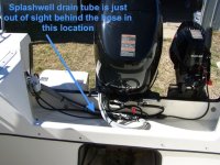
Here is a photo of the whole thing for perspective (not my boat but another, similar 22):

splashwell_overview.jpg

Sunbeam
 
BrentB":2yyx3b17 said:
Thanks
My mistake

But understandable if you thought I was working on a cockpit drain close to the waterline, so I'm glad you brought it up. And I appreciated your comments on the Sharpie since I was already wondering if that was a good choice. Now I'm going to test out the Fusion paint :thup
 
Just a minor update, but I finished installing the new anchor-locker drain clamshell today. First let me backtrack. I had mentioned that there was a small eyenut in the locker that was apparently meant to fasten the bitter end of the anchor rode to. There were a few things I didn't really like about it:

1) It seemed a bit dainty to me.
2) It was attached to the bulkhead between the anchor locker and the V-berth with no particular backing - just a thin finishing washer on the V-berth side (and that's not exactly a massive bulkhead).
3) The hole it went through led into the V-berth (on the level of the edge of the cushions) and the fitting was poorly bedded and bedded on the wrong side only (back of finishing washer on V-berth side was filled with silicone). Any water leaking through would have soaked the underside of V-berth cushions (and as the anchor locker was built, the drain hole for the anchor locker was above the level of this hole).

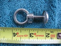
Here's what it looks like:

anchor_locker_eye_nut_1.jpg


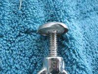
The "bedding" of silicone in the finishing washer (which pulled right off the boat like it was never there; luckily I don't need to try to clean out the washer:

anchor_locker_eye_nut_2.jpg
So anyway, that's removed and I'll fill the hole with thickened epoxy, and probably put a small fiberglass patch on the anchor-locker side (not really necessary, but I'll be doing other stuff with the same materials anyway).

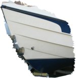
Today I went to put the new anchor clamshell on. I was re-using the apex hole, so I screwed the clamshell into place with that and then marked and drilled small holes in new locations for the other two fasteners (of the two disused holes, one was eclipsed by the new drain hole and the other was previously filled with thickened epoxy and will be under the flange of the new clamshell). Then I removed the clamshell and chamfered the two new holes a bit, and then proceeded to drill them out to the proper size (which is rather larger in fiberglass than wood for a given screw size). I used blue tape "flags" on the drill bits as visual depth stops. Once I had the final diameter and depth holes, I chamfered again to keep the gelcoat from cracking and to give a bit of a well for sealant (not that this particular piece of hardware is a critical seal).

I felt the screws (re-used the ~3/8" long screws from the original clam) could be a tad shorter, so I ground off 3/32" or so from the pointy end. I decided to put a bit of thickened epoxy into the fastener holes before installing the clam -- I have a couple of small squeeze bottles of West System "G/flex" epoxy, and with those it's easy to mix up just a wee batch. I cleaned everything up with denatured alcohol, put a very thin layer of butyl tape on the clam flange and around the base of the fasteners, then mixed up a bit of epoxy and wet out the holes (pipe cleaner), after which I thickened it slightly with colloidial silica and put a bit more in each hole. Then I installed the clam and cleaned up around the outside. Ahhh, much nicer than looking at the drain hole(s)!

bow_with_new_clamshell.jpg

Next time I'm doing something with "regular" epoxy and cloth I'll fill the disused hole from the eye nut.

Sunbeam :hot
 
This is just a parts tale so far, but it may have a happy ending.

So, like a number of other 22's I've seen, mine has the fuel vent fittings right up under the gunwale, with absolutely no room for a proper loop, which means that water/spray has a direct path into the fuel tank. Given that I'm re-doing my fuel system and have the vent hoses off, the idea of just putting them back onto those vents wasn't really thrilling me.

In another thread (http://www.c-brats.com/viewtopic.php?t=19063&postdays=0&postorder=asc&start=30 top of the page), Will-C had recommended a set of Attwood P-trap vents to the original poster. Thing is, I had already looked (longingly) at those vents, but it didn't look like they would fit because they require at least 1-1/2" from the center of the hole in the topsides to the underside of the gunwale (on the inside). On my boat there was a scant 1" :cry
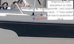
Fuel_vent_original_placement.jpg

Still, I kept looking at them on the Attwood web page, as if wishing could make them fit :D No, actually, I was thinking about potentially carving out a bit of the underside of the deck core to make them fit, or even disusing those holes and making new ones. But wait......look at this page....
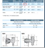
Attwood_1674_fuel_vent.jpg

I've installed flush (non-P-trap) vents before, and because they recess into a dish of sorts, the hole in the boat is necessarily larger. So how could the flush model of the vent (one is flush, the other three are surface-mounted) take the same 3/4" hole as the others? Just to confirm, I looked at Attwood's instructions for the same-style-but-not-P-trap flush mount vent, and lo-and-behold.... it takes a 1-3/8" hole. That's more like it!

Attwood_flush_fuel_vent.jpg

Just to make sure there wasn't something I was missing, I sent an e-mail to Attwood. They confirmed that their web page had a mistake (that they said they will correct) and that the #1674 Flush-mount P-trap vent does take a 1-3/8" hole. You can probably see where I am going with this: If I make the current hole (~3/4") into the new hole, but put all the "new" hole on the bottom edge of the existing one, then I will have a bit more than the required 1-1/2" from the center of the hole to the underside of the gunwale and, Voila, fuel vents that are very water resistant, even though they were put in "too high up" at C-Dory originally (I looked up Attwood's test results and the vents seem very resistant to spray and even water). To top it off, they look nice.

Armed with this encouraging information, I ordered a pair of the vents. They arrived today and I don't see anything obvious that would make them not work (can you tell I don't "trust" boat projects until they are done and I've gotten past any "gotchas"? :lol: ) I'll report back once I've actually tried them in real life.
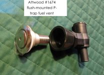
1674_vent.jpg

The black plastic "bowl" you see in the middle goes on the inside of the boat, and then the P-trap screws on after that. The vents come with three different bowls to allow for varying hull thicknesses.

Sunbeam :hot

PS: I put a link in that above-linked thread to this one, so the trail can be followed.
 
Emurph, I was thinking of you as I was typing up the post about the vents. How are you getting on with your fuel system?

Emurph8":3a1ix7v4 said:
I bought 2 of these [fuel fill and vent combos] and am still trying to decide if I am going to use them.

I thought about those too - especially when I was under the impression the P-traps wouldn't fit my boat - but for a couple of reasons decided not to go with combo fittings.

1) I already have vent holes in the topsides.

2) If I remember correctly, Practical Sailor (or someone?) did a review on a number of examples of this type of combo fill-and-vent, and none of them scored very highly.

3) Just looking at how they are put together, I wasn't real confident about how they would keep water out of the vent. I may be missing some key though.

Now that you have them in hand, what do you think about #3?

Sunbeam
 
Everything is coming along nicely. I filled all the holes from the old tanks, I installed the weld man foot loops I have all the hose and clamps and tanks ready to go. I am going to paint the floor with non skid to cover the new epoxy and re do the cockpit floor and under the tanks. As soon as that is done I am going to finish it up. As far as the plastic fill/vent set up, the vent is totally covered by the lid. I'm sure it would work fine. It is all plastic though and I would have to enlarge the hole pretty much to make them work. And to your point I still have the vents on the sides I would have to plug. The Atwood vents you bought look real nice. Where did you get them? I didn't see them on Jamestown. When are you tackling this job? I'm curious how it works out.
Thanks
 
Emurph8":h4ujpcgu said:
Everything is coming along nicely. I filled all the holes from the old tanks, I installed the weld man foot loops I have all the hose and clamps and tanks ready to go. I am going to paint the floor with non skid to cover the new epoxy and re do the cockpit floor and under the tanks.

Sweet! Sounds like you're making great progress. Isn't it nice to know you don't have water potentially seeping into the core?

Emurph8":h4ujpcgu said:
As far as the plastic fill/vent set up, the vent is totally covered by the lid. I'm sure it would work fine.

What I couldn't ascertain (just going by what I could see on the web) is how do they let air in/out, meanwhile keeping water and spray out? I understand how the P-trap works, because it's basically like a dorade vent, but I couldn't "see" how the combo fills work. Maybe you can speak to that now that you have one in hand?

Emurph8":h4ujpcgu said:
The Atwood vents you bought look real nice. Where did you get them? I didn't see them on Jamestown. When are you tackling this job? I'm curious how it works out.

I actually (and rather non-nautically) got them through Amazon. I'm not sure when I'm going to put them in - I've got like seventy-hundred projects going at once, is why. I will try to keep up a project log of sorts in this thread, so unless I'm slacking (has happened) I should post here whenever I do tackle them.

Sunbeam
 
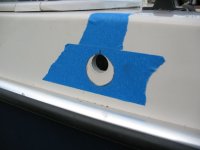
Today I looked over the new vents, played around with them to try to discover any "gotchas" before proceeding, and then got started on the installation. Here you can see how the new hole relates to the old one. I needed to make all the "new" fall below the old in order to have clearance for the P-traps under the gunwale inside the boat. This necessitated using the flush vents (although I think I like them better anyway), since the surface-mounted vents still need the 1-1/2" clearance above the P-trap but would use the original-size 3/4" hole (thus not enough clearance). I did have the option of moving them slightly forward or aft, but they both fell best centered on the old locations.

vent_new_hole_marked.jpg

After I had the hole marked, I taped plastic bags over the inside of the holes (port and starboard) to catch any dust before it got into the boat. I also set up a vacuum on the outside and taped the nozzle in place just above the hole. I first thought I would cut the new holes with a hole saw, so I tapered a 1" dowel so that it fit in the hole with a wedge fit, to guide the mandrel bit, however the center (where the mandrel bit would go) was juuust at the lower edge of the dowel, and when I started to drill a pilot hole for that, I didn't really get a good feeling about how accurately I'd be able to place that center guide hole. So I went to Plan B.

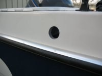
For Plan B, I started with a straight cutting bit on the Dremel (looks kind of like a small drill bit but with finer spirals), and made several "sun ray" lines radiating out from the bottom of the old hole to just a bit shy of my pencil/tape line. Then I connected the "rays" with the same bit, but still shy of the line (no photo because the camera was up in the boat - oops). Next I exchanged that bit for a sanding drum, still on the Dremel, and with that I eased the cut out to the pencil line. Every so often I would test fit the vent. But of course when it doesn't fit (yet), it's hard to know exactly where you need to remove more material (we're talking the fine amounts here, not the gross cutting). So what I did was take a small (1/2") "slice" of PVC pipe that was 1-3/8" ID, and held that up to the hole and then marked on the inside with pencil where I hadn't quite cut enough yet. By that method I got the holes to the right size but kept them tidy and just large enough. (That's also how I marked the holes to begin with.) Here is the new hole just after cutting:

vent_new_hole.jpg

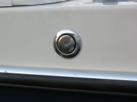
The outside part of the vent set in place in the new hole:

vent_in_place.jpg

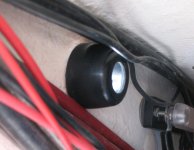
And a view of part of the vent inside the gunwale. This is actually just the largest possible spacer ring (there are three; I can tell I'll be using either this one or the middle-sized one), which shows that it is a bit of a tight fit, but from what I can tell, do-able. The large black "wire" just above the spacer is the steering cable. This spacer ring is not part of the seal - that is made between the P-trap section and the metal part of the vent. This just spaces the P-trap so that as it tightens up on the metal threaded section it also braces itself against the hull side.

vent_backing_spacer.jpg

Sunbeam :hot
 
You didn't waste anytime knocking that out! Looks really good. That is a big hole to cut though. Kind of scares me. My current Vent is below the rub rail so maybe I could get away with the smaller hole version? But then I guess it sticks out which could be a problem? I understand I would need a 4" loop to do it the old way. I don't have that much room I don't think?

The vent/fill I have now would work. The vent hole is under the lid so water can't get to it but you can blow air through it with the lid closed so it doesn't prevent air from moving through. My main concern with it is the extra if hole I would have to cut and the quality of the plastic hinge. If it breaks I'm stuck with the big hole.

The other minor concern I have is my old fill has a broken chain on the lid so I need to del with that and of course I wouldn't have to ground the all plastic fill / vent setup either. I'll have to decide soon. I need to get this done and move on to other things so its ready to get wet in spring!

Thanks for the pics and great info!
 
Emurph8":3v6dalj7 said:
You didn't waste anytime knocking that out! Looks really good. That is a big hole to cut though.

Thanks. It's always a little scary to start, but the way I did it is really controllable, which helps (vs. say, going wrong with a hole saw - not that you would probably).

Emurph8":3v6dalj7 said:
My current Vent is below the rub rail so maybe I could get away with the smaller hole version?

If your vent is below the rub rail, you may not even "need" the P-trap vent. Even if you can't get a full 4" loop, a somewhat lesser loop would likely still do the job (of keeping water or spray out) - as long as it's reasonably "loopy." I basically didn't have room for any loop at all, so the existing vent was just a nice, smooth 90º slide right into the tank - for air or water.

The flush-mounted vs. the surface-mounted vent is usually just a preference thing, to my mind. However with the vents being so high on my boat, the only way to use the P-trap vent (which takes the place of a loop) was to use the flush-mounted one. The larger required hole worked to my advantage and allowed me to fit the vent, while "including" the original hole.

So my guess is that you really have all the options: Flush-mounted or surface mounted "regular old" vent with loop, flush-mounted or surface-mounted P-trap style vent, or vent-n-fill combo.
 
For future reference on enlarging such holes - here's a tip I got from another brat sometime last year. With some hole saw mandrels, you can stack two saws. If the larger saw goes on first the smaller one will stick out a little and serve as a centering guide. If need be, you can use a washer between them to get a little more overhang. It works like a charm.
 
rogerbum":2t5gjmvb said:
For future reference on enlarging such holes - here's a tip I got from another brat sometime last year. With some hole saw mandrels, you can stack two saws. If the larger saw goes on first the smaller one will stick out a little and serve as a centering guide. If need be, you can use a washer between them to get a little more overhang. It works like a charm.

That's a good tip :thup, and it would have worked if the new hole had been centered on the old one. However, since in this case I needed the new hole to be offset from the original one, that trick was not an option.

Sunbeam :hot
 
Back
Top