Need help wiring 30amp Shore Power system

Jazzmanic

New member
I finally got around to installing and wiring the 30 amp Shorepower system. It's basically exactly the same set-up that Ferret30 installed a couple of years ago. Ferret30 shore power recap I tried PM'ing Ferret30 for his insight since I used the same hardware as he did but so far haven't heard back.

I only had a minute to test the system and of course, the outlets weren't working. I didn't have time to run a voltmeter on it but here are the symptoms. The indicator lights for the power and the individual load buttons light up when switched on. However, there doesn't seem to be any power to the loads. I used both of the positions for GFCI outlets. Because I ran out of time, I only completed hooking up the first outlet (with a piggybacked outlet). I'm not sure it's wired correctly even though I followed the wiring schematic. Can you help me figure out what I did wrong?

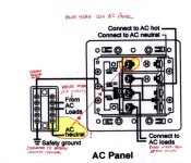
If you look at the schematic for the AC Panel on the left side, it show a dual bus bar. I wired All of the green ground wires, from the inlet, from the AC Panel and from the AC loads (outlets) to the left side of the bus bar. I then ran a 10 gauge green wire to the DC ground.

I wired the two neutral (white) wires from the loads (outlets) to the right side of the bus bar. In the diagram, there is a line marked as "AC neutral" coming down from the last terminal on the right hand side of the bus bar. Am I missing something here? Should there be a wire from the right side of the bus bar (AC neutral) going to DC ground? Or a white wire back to the AC panel? Would the indicator lights not work if the ground was wired properly to DC ground?

I wired the black wire from the inlet to the 2nd screw labeled AC hot on the AC panel. I wired the white wire from the inlet to the top screw labeled AC neutral on the AC panel. I don't see an additional wire going to the bus bar other than the green with yellow stripe wire included with the AC panel. Please HELP!!
Blue_Seas_1214_Wiring_Schematic_001.sized.jpg

One more thing crossed my mind after reading some of the threads on this shore power installation. Is it possible that it's all wired correctly and I just need to really push the reset button on the GFCI outlet? It would be nice if it were that simple.

--- Peter
 
Pushing the GFCI would be my first attempt. After that, with either a voltmeter or an outlet tester, work your way back to the power source to find out where power starts and ends. Note that there was a bad batch of GFCI's out a few years ago that caused some problems so it's possible you have a bad GFCI also.
 
GFI's are very easy to trip when testing or rewiring. The slightest voltage leak (even plain water) can trip them. I'd surely look there first.

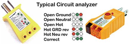
You can buy a relatively cheap tester at any hardware store that will check the wiring simply by plugging them into the outlet in question. The unit will give you a combination of LED feedback lights: various combinations of LEDs that are lit and that are not lit usually tells you exactly how you wired the GFI outlet incorrectly (and other problems such as grounding). These little units look like somewhat oversized 3-prong plugs, and every one I've seen is green.
 
Take Tom Fishing…

First go very slowly--and be sure of every step. You are using 110 volts AC and that can be lethal.

There is no DC involved with the panel you have. There is no real reason to go to the DC negative. What is involved, is the Green wire, is what normally on land is to "Earth" or ground. At your box, and in my case, at the dock. I have a 8 foot ground rod driven all of the way into the ground, and the copper wire to the green wire on the shore side of the circuits to this ground point. The green wire, on the boat is not attached directly to "ground" on the boat. ABYC does call for a common point for the ground circuit--and this is usually the engine block--or in these small boats, the negative battery terminal--not a bus bar. I personally leave the AC ground floating on my current boat--there are several reasons for this--but I have a very simple circuit and much of the time we are running the Honda generator for power, and it floats the ground.

Next-on the boat, you do NOT tie the white or neutral into the green wire or the DC negative or ground circuit. White wire goes to the silver side of the socket--Black wire to the brass side of the outlet.

A really good tool to have to test your boat, and any circuit at the marina to be sure that there is no mis wiring is one of these testers:

Typical-circuit-analyzer-15.jpg

Here is how the plug looks from the front side:
Blue is the white wire, Red is the black wire, and green is ground or green wire.

7_outlet_wiring.jpg

It is very important where the wires go:

3438958_f520.jpg


Because you are on the boat, you are using stranded wire, and 3 conductors (white, black and green) in the vinyl sheath--and crimping ring terminals on the ends of each of these wires. Do not use household wiring or Romex. Before turning on the power, be sure that the wires are correct.

Never confuse the black of the "hot" 110v AC, with the negative of the 12 volt DC circuit. This is why many boats use yellow, instead of black for the negative DC.

The indicator lights on the panel are 110 V AC--and no DC is involved in their function.

If you are still having a problem, take a photo and post it so we can see exactly what is done.
 
thataway":3itrrb26 said:
Take Tom Fishing…

First go very slowly--and be sure of every step. You are using 110 volts AC and that can be lethal.

There is no DC involved with the panel you have. There is no real reason to go to the DC negative. What is involved, is the Green wire, is what normally on land is to "Earth" or ground. At your box, and in my case, at the dock. I have a 8 foot ground rod driven all of the way into the ground, and the copper wire to the green wire on the shore side of the circuits to this ground point. The green wire, on the boat is not attached directly to "ground" on the boat. ABYC does call for a common point for the ground circuit--and this is usually the engine block--or in these small boats, the negative battery terminal--not a bus bar. I personally leave the AC ground floating on my current boat--there are several reasons for this--but I have a very simple circuit and much of the time we are running the Honda generator for power, and it floats the ground.

Next-on the boat, you do NOT tie the white or neutral into the green wire or the DC negative or ground circuit. White wire goes to the silver side of the socket--Black wire to the brass side of the outlet.

Because you are on the boat, you are using stranded wire, and 3 conductors (white, black and green) in the vinyl sheath--and crimping ring terminals on the ends of each of these wires. Do not use household wiring or Romex. Before turning on the power, be sure that the wires are correct.

Never confuse the black of the "hot" 110v AC, with the negative of the 12 volt DC circuit. This is why many boats use yellow, instead of black for the negative DC.

The indicator lights on the panel are 110 V AC--and no DC is involved in their function.

If you are still having a problem, take a photo and post it so we can see exactly what is done.

Thanks guys for the replies. I read in another thread that a C-Brat used a ball point pen to really push down hard on the reset button on the CFGI outlet. I'll give that try. I will also buy one of the testers Dr. Bob posted above.

Bob, I had a question about the ground on the boat. You say you leave the AC ground floating on your boat. Meaning you don't connect it to the negative terminal on the battery? When I was referring to the DC negative, I was speaking about the bus bar connected to the negative terminal from the battery. Wouldn't this bus bar be considered an extension of the negative terminal to the battery?

As for the wiring of the outlets, yes I did as instructed. In fact, I wired exactly the way it was illustrated in the AC panel wiring schematic above. And I used marine triplex 10/3 wire, not Romex. Now I'm beginning to think it has to do with the CFGI outlet so I'll try resetting the button and buy the tester to check the connection. I'll let you know if I'm successful.

And Tom, I don't need you to fix something on my boat to go fishing. We'll just go fishing! :wink

Peter
 
Peter,
It certainly sounds as if you did everything correctly. I go into a bit more detail, because some folks have never done any marine wiring. You can get away with some minor mistakes in the house, but not on the boat.

The reason that ABYC standard is a single point--engine block, is an issue called "ground loops" Probably unlikely in a C Dory, but in more complex boats this can be a real issue. Usually ground loops have alternate paths for electric current to return to ground--or the battery. Mostly this is manifest in audio or radio gear. I have had to trouble shoot a number of cases when trying to find out why ham or marine SSB radio is not working properly, and there is extraneous noise. It can also occasionally be a problem with autopilots. It is best to take that connection to ground at a single point--battery or engine block (outboard negative, which is the battery terminal).

The whole green wire/bonding wire is somewhat subject to controversy. Do you bond all of the thru hulls, or none? The C Dory generally has one or one, and an outboard. It is more important in a boat which is in the water. A lot of this can get mucked up when the marina is in-correctly wired (common), or other boats are in-correctly wired--also common.

The green wire does not normally carry any current, but if there is a fault, it will carry the current to "ground". In your case, all of the circuits should be on a ground fault interruptor, and be broken almost immediately if a fault occurs.
 
We used WR weather resistant outlets outside with bubble cover

When they installed the boat lift they used plain ones and inspector failed the install and replaced with WR

WR work better in wet and damp areas and can handle exposure to direct sunlight

Do folks use WR spec outlet in their boats?
 
Brent,
I have not used the WR in the boat, but I do have them on the boat lift, as well as other outlets around the yard and outside of the house. We even had the boat lift ones under water with our recent fresh water flooding--and they are fine. I checked the wiring for corrosion--and no problems….so far..

After hurricanes, we replaced all of the submerged outlets because there was salt water.
 
I just wanted to follow up on this thread. I'm happy to say that my shore power conversion project is now successful! I figured out where I went wrong with the wiring. As I stated above, followed the wiring schematic to the tee, except for one important step. Remember I was asking above whether the AC neutral from the dual bus bar should be attached somewhere? Well, the answer is yes. It needed to be wired to the negative battery terminal. Once this was done, by way of a bus bar dedicated to negative, the wiring was complete. I also attached the green ground wire to this bus bar as well. It helps that I got one of the testers recommended above by Bob and others. That made things a lot easier because when I first plugged it in, it did show AC neutral as open. Once I closed the circuit by connecting it to the negative bus bar, all was well. I probably could post pictures but it would be no different than any others, showing 2 CGFI outlets, a Blue Seas AC Panel, and the shore power inlet. In any case I was glad to have this project finally done. As all my other projects, it took wayyyy longer than I ever anticipated. Now it's time for boating. I'm done with projects for this season!

Peter
C-Dancer
 
Are you saying that the AC neutral (white wires) are both attached to the battery negative terminal along with the green wire?

I quote from Nigel Calder, Boat owner's Mechanical and Electrical manual:
The neutral and ground circuits are not tied together on the boat--only on shore

The only exception to this (ABYC and NEC codes) is if the "source" of the power is aboard the boat--that is an isolation transformer, a generator or an inverter--and in these cases, the neutral to ground connection is at the source. In your shore power the "source" is the shoreside power pedestal or your house, where the neutral and ground are tied together at either the electrical panel or the dock pedestal--not on the boat.

If it was not working, It makes me think that you did not have the shore power system properly tied together at the source (house mains or marina pedestal) I suspect that you did not have the white wire from the mains current connected to the "dual bus bar you talk about"--if this is the case, then you are completing the circuit thru the ground--and not advisable…

If I misunderstand what you are saying, I apologize.

Here is the proper wiring diagram--note that the neutral and ground are tied at the shore power mains--not on the boat.
shore2.gif
 
PLEASE do not hook up the way that Peter did. Doing this allows all of the return thru the green wire (and the battery circuit)--this potentially energizes the negative battery terminals thru the entire boat. It also energizes the ground wire when a circuit is completed, inside of the boat. If you do this, when an AC circuit is energized, it will have 110V ac thru the cigaret lighter plug, or any of the boat DC negative wiring, if you touch it.

The problem is that Peter did not attach the inner or neutral bus bar to the neutral coming from shore power (white wire). The hot and neutral both go thru the "master" breaker into the boat. His diagram did not make it clear that the neutral bus needed to be attached to the neutral on the boat service side of the master circuit breaker.

Again--do not tie the neutral and ground in the boat, especially when you do not attach the neutral to the shore power neutral! If you do not understand the theory behind the wiring, then please ask for help.
 
Bob,

One more thing, I believe that if the neutral is attached to the ground on the boat side, you have serious potential for increasing galvanic corrosion - correct? E.g. the return current from the A/C hot can now leak into anything connected to the boat's battery ground (which will likely include the zincs and other metals on the boat). Am I wrong on this?
 
Roger, you are correct. This has another serious effect--and that is that anyone swimming who touches the metal gets a chance of a shock--or worse. Also even swimming close to the boat, may get a shock. Other boats in the vicinity can also have serious electrolysis issues.

There are a number of ways a boat can be miss wired, and this is only one of those, which has serious effects. Connecting hot to neutral is a common mistake, which gives the same effect as this error. In some ways more serious, since it will always be hot, not just when an appliance or light is turned on. The ground and neutral is also another common mis-wiring error.
 
Once again, thanks to Bob for hanging in there with this wiring novice. He was absolutely right, I closed the circuit to the AC neutral by grounding it, which is WRONG! You're right as well Roger.

After I saw Bob's diagram above, I realized the AC neutral loops back and saw I had a AC neutral terminal that hadn't been used and figured that it's purpose was to close the circuit. The problem is, the wiring schematic supplied by Blue Seas does not show where to terminate the AC neutral wire off the dual bus bar. Once I thought about it, it made common sense to connect it to that terminal. I ran up to the boat during lunch, disconnected the AC neutral wire from the negative bus bar and reconnected to the neutral terminal on the AC panel and voila, all is working and is now correctly wired.

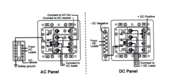
Once again, thanks guys for hanging in there with me. Now I can accept your compliment Mark since it is now wired correctly and more importantly, safely. Below is the "correct" wiring diagram.

Blue_Seas_1214_AC_Panel_Schematic_B.sized.jpg

Peter
 
Peter,
Thanks for posting your corrected diagram. It is a puzzle to me why Blue Seas did not make it clearer on their diagram that you had to connect the AC neutral to the boat side of that main switch?

Good job, and we can now rest assured that the boat is safe!
 
This thread will help me a lot for my install. I originally thought i would not need the bus bar to instal due to not having DC power I see now from this thread that I will in fact have to install the bus bar. also will the bus bar need to be tucked inside the box cover too or leaving it exposed ok to do? I got the blue sea back cover for this and not sure they will both fit behind it?

originally i looked at this diagram and figured it could be ran without a bus bar
http://amit.nightmarebeforechristmas.ne ... 343760.pdf
 
Back
Top