Mixed wire sizes

Aurelia

New member
If I had a 30ft run made up of three lengths of wire each 10ft long, butt connected in 6 then 8, then 10 gauge, is the maximum amp rating based on the smallest wire or an average of the three? Do I get "credit" for the lower resistance of the larger lengths that applies to the smaller length?

I don't know the answer and I am not sure it is simple or simple to find.

Greg
 
The weakest link in the entire system would be the thinnest wire. That would be your "fuse" in the set of three for that run if currents got away from you. The entire run would be limited by the current-carrying capacity of that thinnest wire. The others would not help.

The "advantage" of the thicker wire sections would not be the current-carrying capacity, but the voltage drop at the other end. There would be less drop in voltage than if the entire run was made up of only the thinnest wire.

The above assumes "perfect" connections between the three sections, however. This is likely never the case, and what you might make up in voltage drop by having thicker wire sections would just be lost by inefficient connections between them.

JMHO,
Ray
 
Voltage drop = current in amps x resistance in ohms.

For copper wire, standard AWG, at 22 degrees C.

for 10 feet of wire #6 AWG= 0.004 Ohms, for # 8 AWG= 0.006 Ohms and for # 10 AWG = 0.01 Ohms

All of these are available on the internet, or in a very handy pocket publication: Thomas J. Glover Pocket Ref.

You have less resistance in larger gauge of wire. The limiting factor would be the thinest wire, as Ray noted.
 
interesting question, there are numerous charts (the west marine site has one) that show conductor voltage drops for a given amerage. I would think you would want to determine the voltage drop, given your amp load, for each ten foot section & then add the voltage drops up. If the sum is agreable to the component, you win.

some thoughts-

Keep in mind that if it is 15' from supply to the component, you would have a 30' run...15' of hot & 15' of not

the gauge of the conductor needed is dermined by the length of the run and the amp load. A larger gauge conductor than needed only gives you more weight and cost

I just googled up a wire gauge chart and it shows that 10' of 6 gauge wire can safely handle 90-100 amps with a less than 5% drop so unless you're running an arc welder, it should be good
 
Well, let's combine what Bob and Ray said because there's 2 answers, depending on what the question is.

First, the current carrying capacity for the smallest wire is the limiting factor as far as maximum current. The standard current carrying capacity for wires may be found here: wire ampacities . As the page points out there's a lot of different factors, primarily related to heat. For the smallest dia. wire (10 ga), that capacity is 15 amps for power transmission. Voltage doesn't count, current is the limiting parameter. Note that in different applications, the maximum current recommended may vary, these are just guidelines.

Here's the West Marine wiring chart. Note they allow more amperage than the reference above.

Next, the end-to-end voltage drop. The same reference as used above gives the resistance drop for 1000', which agrees with Bob's numbers. So, the 10 ga has 0.01 ohms, the 8 ga, 0.06 ohms and the 6 ga, .004 ohms for a total of 0.02 ohms. So, yes you're getting credit for the larger dia. wires (smaller ga.)

Now for the voltage drop. Remember E=IR. Since you don't mention the application or voltage and current, all that can be said is that the 10 ga wire will have 1/2 the voltage drop in 10 ft. and the remaining 20 ft will have the other half. That's your credit for that 30'. If you want the round trip voltage drop, add in the return wiring length.

Boris
 
This is not a real situation for me Tom. I am trying to gain a better understanding of the factors involved in the ratings and this mixed wire question does relate to real situations on boats that are not well covered or charted.

I am often more interested in what could be done than what should be done but I also don't like burning boats to the ground with any regularity.

Thanks for the input so far and I will be doing more reading and maybe a little testing on this. The connections are an obvious weak link but that is hard to avoid.

Greg
 
It's almost like a water pipe. Different sized pipe would limit the flow to the smallest pipe used. Same with an exhaust system on a car. Flow limited to the smallest size pipe used. Wire is rated for amperage load. In a home if you are using a twenty amp breaker or fuse the wire needs to be sized accordingly 12 gauge using smaller wire can heat up and cause a fire. A 15 amp breaker you could use 14 gauge. Direct current draws more amps because of the low voltage.
D.D.
 
Dave's post brings out an important point--also touched on with Boris's. The voltage makes a huge difference in wire size. (I had touched on that in both this thread and the moving the battery thread --where 24 volts is sometimes used to lower the wire size, and the fuse size. Many of the new boats which are going all electric are going back to higher DC voltages.

The type of conductor material: copper, aluminum, steel makes a difference in the resistance--and what size is adequate.

Also ambient heat makes a difference. If the wires are bundles with a number of other wires, where the heat may rise, this also makes a difference. Resistance changes (Increases) with heat. note in my first post, I mentioned the material of the wire and the temperature. Also the type of wire is important: AWG, Tinned, multiple strand, stand size, as well as the type of jacket--all reflect on the carrying capacity.

Greg's question does have practical application--because there are many times when we may have #2 wire from the battery to the first fuse/breaker, then a bus bar, with several branches of #6 to #10 wire. After the bus bar in the console, there will be wires from #12 down to as low as #22.

Connectors are also hugely important. We recently discussed crimps--and other connections. It was implied in Greg's question that these were good connectors--but the best conectors have strain relief, good contact, corrosion prevention, support of the wire/connection.

Although it is not generally recommend to solder boat connections--there are some I do. For example, going from the wire on the Windlass to the #6 wire--I don't have a reducing connector for that size. So I did the best crimp I could, and then filled the crimp with solder. Then put adhesive heat shrink over over the connection. I have done this with some of my large lug connectors. The thought being that I have less chance of corrosion if water gets in there. However I have a good crimp first. Finally there are some wires which just don't lend to a crimp connection. For example I had a rotary switch for selection of the various batteries on the Tom Cat--(2 Start, 2 house, two freezer, so I needed a rotary multiple pole switch, which had small connectors which could only be soldered.

It is also good to occasionally check the temperature of wires (using IR)--as well as the voltage in places where there are open spade or bolt connectors, to check for corrosion as well as adequate conduction. So many times an electrical problem in a boat is due to corrosion of a wire--often ground or negative.
 
thataway":1zj660eo said:
Although it is not generally recommend to solder boat connections--there are some I do. For example, going from the wire on the Windlass to the #6 wire--I don't have a reducing connector for that size. So I did the best crimp I could, and then filled the crimp with solder. Then put adhesive heat shrink over over the connection.

I was just wondering how I was going to make that connection, and how others have done it. I decided I had probably better not start another wiring thread at the moment, but then you mentioned that exact connection! I was looking at a web store where I usually buy my crimps and lugs, and really didn't see anything for joining #6 cable to ... I think we decided it is #8 or #10 on the windlass (forget at the moment). I was wondering what were good options for this. Is this a place to use a terminal block? Two power posts? I guess you found some sort of butt connector that would join the two before soldering...

Edited to add: I do see that Blue Sea has a 2 position, 65 amp terminal block with #10 screws, and FTZ has "starter lugs" for both #8 and #6 that have #10 rings on them. So I guess that is one option.

Sunbeam
 
I prefered not to have a terminal block in this area, which can get corrosion, has chain which is exposed and under certain circumstances hit the block, (although it would not be energized) unless there is a secure cover for this block--

I used a #6 bare butt connector, bent back enough strands of the wire from the windless, to make it tight when pushed in to the connector, then crimped, and made a dimple in the middle of the crimp. This was mechanically tight. I then used a small torch to heat the exterior of the butt connector and sweated solder in from both sides. After this I slid the adhesive lined shrink wrap down over the connector.
 
When I removed my windless for service I used two split bolt connectors or what most call a bugs. It's a jaw type connector that you can connect two different sized wires and tightens down the jaws with a nut on a split bolt or a bolt that clamps the two jaws together. Common practice is to first tighten the two wires in the connector then wrap with friction tape and then finish with a good brand of electrical tape. This allows for removal at a latter date without soldering cutting etc.. I always try to stagger splices so the connections are not side by side. It seemed it would be easier down the road if I wanted to remove the windless for service etc. Available at W.W Grainger or any electrical supply house.
D.D.
 
Wise or not, I'll leave to others...but where a butt connector needs to join wires of different sizes it's pretty simple to address.

Simply strip back twice the normal amount of insulation on the smaller wire, twist and fold the exposed wire back over itself, snug it into the larger butt connector and crimp. If there's a double crimp that secures the connector on the insulation side, adding shrink wrap to the insulation can increase the diameter there.

Haven't had a need for such a hack on the boat, but have done it many times elsewhere without issue.

If anyone needs me, I'll be playing banjo on my porch.
 
A few comments on wires and wiring. Sorry for the lecture, but this is basic electrical stuff.

First voltage as such doesn't determine a wires capacity, amperage does. The voltage drop through the wire is only dependent on the wires resistance and the current: delta E = IR , regardless of the input voltage. And the power lost is Power = I^2 x R, current squared times resistance.

One can reduce the current by increasing the voltage AND CHANGING THE LOAD. Power = EI and if you increase the voltage, that load (electronics, motor, whatever) had better be able to use/withstand the increased voltage. Going to 24 VDC from a 12 VDC system means one must go to 24 VDC equipment.

Yes, one can cut the current by increasing the voltage. High voltage is used in power transmission lines where the voltage can be as high as 750 KV. This comes from Power = I^2 x R, so if you want to transmit power, you can cur the resistance losses by increasing the voltage which decreases the current. For power transmission, there's a big payoff since the power levels are high, not so much for a small boat

And for an equivalent AC (RMS) or DC current the capacity is the same since the resistance is the same.

Finally, a properly soldered connection is the best from electrical and structural considerations. Solder (tin and lead,) doesn't corrode near as much as copper. Problems have occurred from flux residue. The reason that crimped connections are used in high reliability applications such as spacecraft, is inspection. One can easily inspect the crimped connection, but the soldered connection needs an internal view which is hard to get. So if you want to solder go ahead; and one should solder high current terminals, such as battery cables. I spray ALL connections outside the cabin with Boeshield, works well. And terminal strips allow neat wiring, look at the back of the terminal panel on your C-Dory.


Boris
 
I have been reading and thinking but this question still leaves me unsure and I have not found additional good explanations at least in 12v situations thus far.

Lets use just one example set of wire charts as a reference, not saying they are the best or worst, and give it capacity number as a 30ft length.

http://www.westmarine.com/WestAdvisor/M ... d-Ampacity

My theoretical three size 30ft length of 6,8, and 10 AWG wire could handle...?

Up to 60A at 10% drop or 35A at 3% drop? (smallest wire limit at 10ft length of 10AWG)

Up to 41A at 10% drop or 12A at 3% drop? (smallest wire limit at 30ft total run length)

Or is it really somewhere in between?

Un-hijacked,

Greg
 
We have to clarify if this is a 30 foot round trip--or 30 foot one way?

Assuming 10 foot one way (or round trip circuit 5 feet each way). The West Marine table is a very rough way to figure. Using this table, what you say is true for the single wire. If you add in the different resistances, which can be calculated for each length of wire, as per the formula I gave in my first post, then you could calculate how much voltage drop--figure that back to % and then come up was an answer which is somewhere in-between the two values as in your question.

Far better is the Blue Seas Circuilt wizard:

http://circuitwizard.bluesea.com

This is far better, because it takes into account wire size, run, voltage, temperature, insulation, fixed vs variable load, engine room temps, etc. It is also available as an app! This has been developed by Blue Seas Electrical Engineers and is also compliant with ABYC standards, which is where you want to be for safely. It is more than just voltage drop!

Taking 10 feet by pure voltage drop capability, 10' (round trip 5 + 5) at 3% #10 wire would be suitable. If you take all of the factors by Blue seas engineers, and ABCY it would require #8 AWG wire. (Variable, 60degree insulation, non engine room)

At 10% voltage drop only, 10 feet would be OK @ #14 AWG, but recommended by all other criteria would be #8 AWG!

If you take this out to 30 feet round trip--or 15 feet each way: it would be recommended at 4 AWG, and by some ABYC standards could be #8

If you take this out to 30 feet, round trip: 15 feet each way:
and 10% drop: Voltage drop only AWG 10, but all factors AWG #8…

So you see it is not as clear cut if you really want to go with the ABYC best recommendations:


Take this to 44 feet, which is the windlass length for most 22's--the
3% comes up with: #3 AWG
And 10% comes up with 8 AWG

The recommended #6 AWG wire allows for a 7% voltage drop at 44 feet.

By Blue Seas Calculations: Max amps allowed in any length of #10 wire is 60 amps. But this would only be for a very short run.

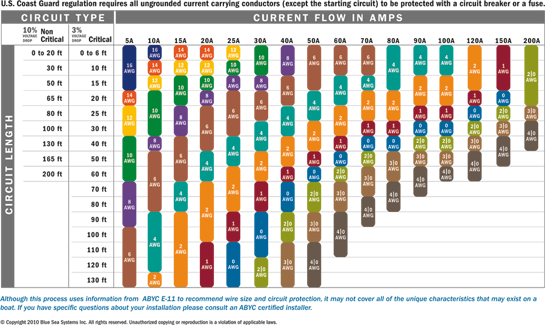
Blue seas puts out another nice table, Called finding the correct size of wire for DC circuits:

http://www.bluesea.com/resources/1437

DC_wire_selection_chart.png
 
"an answer which is somewhere in-between the two values as in your question"

Perfect Bob. My understanding was leading me to the same conclusion but the variables involved make precision tough and that I can live with. Too many things I read provide specific requirements of this or that but never address the why or gaps between the prescriptions. I feel more comfortable now in judging the safety of a curcuit and whether or not something installed in a given boat should get attention.

I have seen the Blue Seas chart before but it seems a bit conservative and does not for instance list 10g as even being an option for a 40a load although you and I know it could take at the 0-short distance the chart claims to include.

The wizard is great and I had not ran into that one. Thanks for the link and I will be using that one on occasion.

Greg
 
Back
Top