| View previous topic :: View next topic |
| Author |
Message |
CharlieRock
Joined: 13 Jan 2017
Posts: 18
City/Region: Celebration
State or Province: FL
C-Dory Year: 2006
C-Dory Model: 23 Venture
Vessel Name: Charlie Rock
Photos: Charlie Rock
|
 Posted: Sun Jan 31, 2021 9:40 am Post subject: 120v Inverter/Shore Power switch or relay? Posted: Sun Jan 31, 2021 9:40 am Post subject: 120v Inverter/Shore Power switch or relay? |
 |
|
Looking for electrical, safety or power efficiency insights on 120v wiring. I just upgraded our Inverter to a 2000w PSW Renogy. I replaced the Wallas stove with an Induction stove, and am adding a Microwave under the Forward dinette seat and a portable Fridge under the table. I just wired in a 120v outlet (lots of bad words getting the heavy gauge wires under the flooring to follow the path of the water lines from tank to sink). Under the galley I have 2 outlets, one for the inverter and one for Shore Power (there is probably an efficiency to combine them). Looking for recommendations on a switch, relay, converter or recommended device, so that the dinette outlet, can be connected to the inverter (primarily microwave or MacBook power), or Shore Power (for the Portable fridge when at the dock.
_________________
Tim Fahy
Home Port Celebration Florida
C Co. 1/187th AARCT
Charlie Rock (former Noro Lim/Journey) 2006 CC23
Charlie Rock 2017 Ranger Tug R23 2017-2020 |
|
| Back to top |
|
 |
B95054
Joined: 19 Nov 2020
Posts: 27
City/Region: Maple Ridge
State or Province: BC
|
| Posted: Sun Jan 31, 2021 10:45 am Post subject: |
|
|
You will want to use a manual transfer switch. A single circuit 15amp is all you need. I have a Hubbell GENSWITCH515 wired into my house for power outages and if I remember correctly it was less than $100 CAD. It will isolate the two power sources so that you cannot accidentally run both shore power and inverter power at the same time.
_________________
Discovered the C Dory and think it will be my next boat. Currently looking for a good 23 foot cruiser. |
|
| Back to top |
|
|
thataway
Joined: 02 Nov 2003
Posts: 21473
City/Region: Pensacola
State or Province: FL
C-Dory Year: 2007
C-Dory Model: 25 Cruiser
Vessel Name: thataway
Photos: Thataway
|
| Posted: Sun Jan 31, 2021 11:42 am Post subject: |
|
|
I would use an automatic transfer switch: Here is an example. Magnum is well thought of in the inverter world.
A 30 amp auto transfer switch is here
A few other thoughts: What batteries are you going to use and where are they going to be located? Be sure that the water heater and battery charger are not on the auto transfer switch current. If you are going to run both the inverter and microwave, at the same time, then you will want a 30 amp transfer switch.
You will want at least 100 amp hours usable battery power (either 2 AGM group 31's or one 100 amp LiFePO4 battery, and a way to rapidly recharge the batteries). You will need heavy cables--at least 1/0 up to 4/9 battery cables from the batteries to the inverter.
Then you will have to rewire the 110V plugs that are going to run the induction burner, microwave and refrigerator so they are all going thru the inverter. All of the 110 wiring, should be 12 gauge Marine stranded wire, not romex solid wire as used in household wiring.
I have done this on two boats. There are two ways to do it. The Tom Cat, I just put in split 110 V 15 amp outlets, so that when I was on inverter power, I used one side of the 110 V outlet, and mains power the other side. this gets away from completely re-wirng the boat. On my current 25 C Dory, I am using a 2000 Watt PSW Victron Inverter/80 amp charger/50 amp power booster, which has a built in transfer switch. (Much easier to use an inverter with built in transfer switch.)
In the latter case, I too power from the main 110 V panel, off the "outlets" and ran it to the inverter. then I ran the wire back to the main panel, where the inverter is now hooked up to all ov my 110 V outlets (except the air conditioner, Battery charger and water heater are all on separate 110 V circuits from the main power panel.
The Tom Cat I put in 2 AGM group 31 batteries about 2 feet from the inverter. The C Dory 25, I have 2 Battle Born, 100 amp hour LiFePO4 batteries. I found that I needed ore than 100 amps usable. I also run 12 volt refrigeration (two top loading chests; one a freezer and the other a refirgerator.).
Your way is very similar to what I did with the Tom Cat. I am not a fan of a the output from an inverter being thru a 110 V duplex outlet. Hard wiring is safer, and I believe to ABYC standards for permeant installation.
For the computer, you are probably better using a small inverter-such as 150 watts. The MacBook only draws about 60 to 85watts depending on model.
The microwave will probably pull 1000 watts. (I know that some microwaves are labeled "700 watts", but that is output, not input. If you don't already own a Kill-A-Watt meter buy one. It will show the power draw of any appliance, in watts, amps and cumulative over time watts, plus voltage and hz (cycles).
You also want a shunt type meter for current draw to the inverter. The Victon 702 or 712 (blue tooth to I phone, makes it slightly easier to use). I don't know what the charging output of your Yamaha outboards are--but it will need all of the power to recharge the inverter battery bank.
Draw out your circuit before you start running wiring.
_________________
Bob Austin
Thataway
Thataway (Ex Seaweed) 2007 25 C Dory May 2018 to Oct. 2021
Thisaway 2006 22' CDory November 2011 to May 2018
Caracal 18 140 Suzuki 2007 to present
Thataway TomCat 255 150 Suzukis June 2006 thru August 2011
C Pelican; 1992, 22 Cruiser, 2002 thru 2006
Frequent Sea; 2003 C D 25, 2007 thru 2009
KA6PKB
Home port: Pensacola FL |
|
| Back to top |
|
|
B95054
Joined: 19 Nov 2020
Posts: 27
City/Region: Maple Ridge
State or Province: BC
|
| Posted: Sun Jan 31, 2021 1:25 pm Post subject: |
|
|
Great points above. However a 2000 watt inverter only puts out a maximum of 16.6 amps so a 30 amp transfer switch is overkill. It wont hurt anything but is unnecessary unless you plan to run a larger generator or inverter at some point. 15amp is sufficient.
Those Magnums appears to be at a very good price point! |
|
| Back to top |
|
|
thataway
Joined: 02 Nov 2003
Posts: 21473
City/Region: Pensacola
State or Province: FL
C-Dory Year: 2007
C-Dory Model: 25 Cruiser
Vessel Name: thataway
Photos: Thataway
|
| Posted: Sun Jan 31, 2021 5:11 pm Post subject: |
|
|
| B95054 wrote: | Great points above. However a 2000 watt inverter only puts out a maximum of 16.6 amps so a 30 amp transfer switch is overkill. It wont hurt anything but is unnecessary unless you plan to run a larger generator or inverter at some point. 15amp is sufficient.
Those Magnums appears to be at a very good price point! |
Most of our boats are wired for 30 amps from the factory--they have water heaters, battery chargers and then circuits which have breakers for 15 amps. So that input power to the boat could be well over 15 amps. So it depends on how you wire the boat. My inverter with will actually hand 50 amps, and will boost surge (synchronizing with mains current) to 50 amps if needed.
You don't want to undersize transfer switches. If you are certain that you nor anyone else will use less than 15 amps--then OK. But it is the appliances which may be used, and how the boat is wired. |
|
| Back to top |
|
|
B95054
Joined: 19 Nov 2020
Posts: 27
City/Region: Maple Ridge
State or Province: BC
|
| Posted: Sun Jan 31, 2021 5:56 pm Post subject: |
|
|
With all due respect....
Sizing is done according to his inverter and load size and not the shore power size. He is wiring one receptacle into his boat and therefore only needs one circuit of power. His 2000 watt inverter will put out 16.6 amps of constant current (ohms law. 2000w divided by 120 volts). He may add additional outlets on the same circuit but available current is limited by his inverter size.
The 50amp of your Victron requires the presence of shore or generator power to get to 50 amps. It allows for the supplement of battery power for short term additional load requirements when you have maxed out your 30 amp shore power. That is not what the OP is looking for since he is using a 2000w Renogy pure sine wave.
He absolutely should not overload his inverter so to properly wire a 30 amp transfer switch he would only wire one of the two circuits and leave the other circuit unwired.
I stand by my statement that a 30 amp can be used but is overkill however I will add that wiring should only be done to a single circuit only. Or just buy a 15 amp transfer switch as I suggested.
Btw it has not been discussed but there a different camps on the merits of manual vs automatic. Personally I prefer manual as one more method of control for phantom current draw and it does not bother me to flip a switch when I want power but also appreciate the convenience of automatic transfer switches as well. |
|
| Back to top |
|
|
smckean (Tosca)
Joined: 18 Jan 2014
Posts: 975
City/Region: Guemes Island (Anacortes)
State or Province: WA
C-Dory Year: 2005
C-Dory Model: 25 Cruiser
Vessel Name: Tosca
Photos: Tosca
|
| Posted: Sun Jan 31, 2021 6:37 pm Post subject: |
|
|
I'm not sure I understand the desired power configuration, but if all that's desired is to run some units/outlets either on shore power or off an inverter at the users discretion, I just finished such a project. I don't know if I did it 100% properly, but I know that I did it simply.
For each desired 120v driven unit/outlet, I simply installed a 120v 15amp DPDT toggle switch (other types of switches could be used too, e.g., rocker). I wired the unit to the center 2 lugs of the DPDT toggle, then shore power (from the panel) to one set of outside lugs, and inverter power to the other set of outside lugs. So I just throw that toggle switch to shore or inverter depending on what source I want to use for that unit/outlet at that time.
The shore and inverter circuits for any unit or outlet are completely separate. There is no interconnect between the 2 power sources at all. That's one reason I used DPDT switches instead of SPDT switches.....I didn't even want to share the neutrals. Note I have no need for a transfer switch since the DPDT toggle switch can only be in the one position or the other (never both). This setup also gives me total flexibility since I can power any unit/outlet from any source independently of how I am powering any other unit/outlet.
Clearly, this setup only makes sense for a small number of units/outlets since I have to run wires from the inverter to all the units/outlets for which I desire dual sources (effectively double wiring). If there are lots of units/outlets, it would make more sense to bring both sources of power to the panel and use the existing wiring (requiring the transfer switch) as has been described in other posts.
P.S. One nit puzzled me in doing this. What to do with the ground wire on the inverter circuits? I finally realized that on a plastic boat not connected to shore power, the ground floats so the inverter ground is not connected anywhere.
_________________
Sandy McKean
Purchased Tosca in 2014
Re-powered to Yammi 200 in 2015 |
|
| Back to top |
|
|
B95054
Joined: 19 Nov 2020
Posts: 27
City/Region: Maple Ridge
State or Province: BC
|
| Posted: Sun Jan 31, 2021 7:31 pm Post subject: |
|
|
Oh boy, I am not making any friends here today 
On shore power you are grounded to earth but on inverter power you rely on a bonded ground to neutral. The DPDT switch does not allow for a proper bonded ground to neutral. That is why you need to use a transfer switch. Floating the ground on your own creates a safety risk with no backup fusing which is why it would violate the electrical code and AYBC standards. In other words it could nullify your insurance if it were deemed an incident was caused by incorrect wiring and lack of fusing. In one of the posts above there is a link for a $40 transfer switch. That seems like a pretty low price to not invalidate insurance and create a potentially dangerous situation. |
|
| Back to top |
|
|
robhwa
Joined: 04 Dec 2013
Posts: 298
City/Region: Anderson Island
State or Province: WA
C-Dory Year: 2003
C-Dory Model: 22 Cruiser
Vessel Name: Marcia C
Photos: Problemadela
|
| Posted: Sun Jan 31, 2021 8:21 pm Post subject: |
|
|
What do youall think of this unit?
https://www.renogy.com/3000w-12v-pure-sine-wave-inverter-charger-w-lcd-display/
There is a 2000w and newer 1000w model as well.
It is an inverter/charger combination with an automatic transfer switch. When AC power goes out, it switches to battery inverter quicker than you can notice. It can also "close" grounding when switching to battery inverter from shore.
I bought one of these originally so that when power went off in my greenhouse, the pellet stove (which heats it) would continue to work, as I could lose all of my veggies overnight or if I am not here.
If the power was off for an extended period, I could hook up my generator and run for a bit while recharging the batteries at 75 amps (65 amps for the 2000w). Worked great so far for several months and several outages. I've also run the batteries down a few times and then used line or generator to recharge to test it. Recharging is fairly quick with the LiFePO4 batteries I use.
So, I got two more at a discount (dented and scratched) for a good price. I had about 3 months to test them, and all worked. I've tested one in my C-Dory 22 with 2 LIFePO4 100amp batteries, and though heavy, it works great so far.
To me, this seems a very flexible system, particularly in the winter PNW (not getting much from solar) when you have a generator or shore power and use a lot of 120 VAC. I run my trolling motors a lot, and this system can nearly keep up when a generator is running.
Any concerns?  |
|
| Back to top |
|
|
thataway
Joined: 02 Nov 2003
Posts: 21473
City/Region: Pensacola
State or Province: FL
C-Dory Year: 2007
C-Dory Model: 25 Cruiser
Vessel Name: thataway
Photos: Thataway
|
| Posted: Sun Jan 31, 2021 8:43 pm Post subject: |
|
|
Not directed to any specific post,
I have concerns with inverters which are not built to marine and ABYC standards.
I am concerned with fusing (DC type T fuse), Terminal and lug size, , and wire size--both for DC, grounding case, type and size of AC wiring. The use of proper switches and terminals.
These inverters use a lot of power. They need temperature sensors for the batteries, they many need forced ventilation (for example fans to remove heat from the area where they are installed), They may need shock mounting.
The concern is safety. |
|
| Back to top |
|
|
smckean (Tosca)
Joined: 18 Jan 2014
Posts: 975
City/Region: Guemes Island (Anacortes)
State or Province: WA
C-Dory Year: 2005
C-Dory Model: 25 Cruiser
Vessel Name: Tosca
Photos: Tosca
|
| Posted: Sun Jan 31, 2021 10:27 pm Post subject: |
|
|
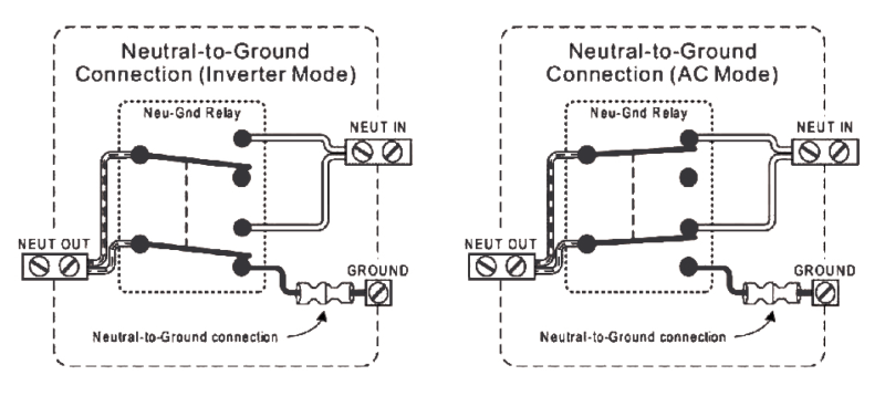
| B95054 wrote: | | The DPDT switch does not allow for a proper bonded ground to neutral. |
Could you explain this a bit more?
I probably didn't make myself clear. First, I used 14-3 marine stranded wire cable to do this wiring. All the green ground wires are connected to the outlets (which means the shore power and inverter power greens are interconnected). The black and white wires are switched, but which ever position the switch is in, the situation is exactly the same as if the black and the white were a single piece of wire -- having the switch there would be the same as if I cut each wire and then just twisted the ends back together.
One thing I failed to mention is that if I am plugged into shore power, I never use the inverter. OTOH, while at anchor I sometimes use both the inverter wiring and the standard 120v wiring energized by my generator. In that situation neither the boat nor the generator nor the inverter have any connection to ground; so I couldn't see how my project could harm anything. The one thing I did not do is ground either 120v wiring to the 12v negative. I figured that would be a mistake for sure since then metal surfaces on the boat could be at the potential of the earth (although poorly bonded via the salt water) via a malfunction in the electrical system of the engine . |
|
| Back to top |
|
|
B95054
Joined: 19 Nov 2020
Posts: 27
City/Region: Maple Ridge
State or Province: BC
|
| Posted: Sun Jan 31, 2021 11:03 pm Post subject: |
|
|
Certainly
There is a big difference with grounding between shore power and when running off of a generator or inverter.
First to explain this properly we have to understand why to ground in the first place. It is there to protect you and your appliances from surges. For the most part an electrical circuit is balanced but when something goes wrong ... like a surge...the is a huge amount of excess electricity and that additional electricity has to go somewhere - hence the ground. We are all guilty of bypassing that third prong on extension cords at some time and everything works. But the ground is there as a safety device and if something goes wrong you risk injury or fire.
So now back to the difference between shore power and locally generated power.
On shore power that ground is wired to a rod that goes into the earth and that excess electricity (if it happens) goes into the ground and disperses.
In the case of a generator or inverter you dont have the luxury of wiring into a rod driven into the ground so you have to come up with another plan. So what they do is bond the ground to the neutral and the protect it with a circuit breaker or fuse. This means that if a surge happens the excess energy follows the path of the ground and which then trips the breaker or blows the fuse thus dispersing the excess energy. This is what is known as a floating ground.
No ground at all is the equivalent of cutting that third prong off of your extension cord and eliminates all of this security ....but that surge of electricity still has to go somewhere. Electricity always takes the path of least resistance so it either fries up the wires in the appliance or worse yet finds its way into the human that is holding the tool or appliance. That is why you need a purpose built transfer switch which has been designed to incorporate all of the safety features of both the shore power ground or the locally generated powers floating ground. |
|
| Back to top |
|
|
robhwa
Joined: 04 Dec 2013
Posts: 298
City/Region: Anderson Island
State or Province: WA
C-Dory Year: 2003
C-Dory Model: 22 Cruiser
Vessel Name: Marcia C
Photos: Problemadela
|
| Posted: Mon Feb 01, 2021 12:02 pm Post subject: |
|
|
| smckean (Tosca) wrote: | | B95054 wrote: | | The DPDT switch does not allow for a proper bonded ground to neutral. |
Could you explain this a bit more?
|
Like this?
 |
|
| Back to top |
|
|
journey on
Joined: 03 Mar 2005
Posts: 3599
City/Region: Valley Centre
State or Province: CA
C-Dory Year: 2005
C-Dory Model: 25 Cruiser
Vessel Name: journey on
Photos: Journey On
|
| Posted: Mon Feb 01, 2021 12:41 pm Post subject: |
|
|
Power surges in your house are a part of life and the equipment being powered has to handle it or be ruined. Power surges have nothing to do with the green wire. Also, my inverter has a transfer switch builtin; check yours.
That green wire is there to ground the chassis, the structure which supports the electrical equipment. It has 2 functions: one is to eliminate the noise on the chassis and the other is to provide a ground path if the power return shorts to ground. The GFCI receptacle does this by comparing the input current (black wire) with the power return (white wire) to to make sure they're the same. It's assumed that the current difference goes through the chassis ground (green wire).
In a house, both the power return and chassis ground are earthed, often at the same place. If you tie them together in a boat and and connect shore power,the dock GFCI will disconnect the power.
I use terminal strips to power my computers. They smooth out the power surges, which are voltage surges. I also ground the chassis on my instruments in order to reduce the stray voltages/currents.
Boris |
|
| Back to top |
|
|
|
 Search
 Private Messages
 Profile
 Log in
 Register
 Help
Help
