| View previous topic :: View next topic |
| Author |
Message |
JMacLeod
Joined: 26 Jun 2018
Posts: 173
City/Region: Stuart
State or Province: FL
C-Dory Year: 2018
C-Dory Model: 255 Tomcat
Vessel Name: C-Shalom
Photos: JMacLeod
|
 Posted: Wed Oct 10, 2018 9:34 am Post subject: Posted: Wed Oct 10, 2018 9:34 am Post subject: |
 |
|
That is some serious next level coolness, Bob.
Cheers! 
When I realized I was going to have to replace the new house bat if I wanted to add an AGM, I looked at the LFP option too.
I compared the Renogy, Battle Born, and Mighty Max LiFePO4 batteries available on Amazon, and even BRIEFLY considered building my own out of about 300-400 ah of individual 3.2v cells (ecigs) I have in the garage.
The Battle Born was most expensive, but got the best reviews by far and was certainly the most responsive to their customers.
You chose wisely in my book.
So many questions, but that's for another day.
Today you've much bigger, category 4 concerns.
Hurricane season has decided not to go out with a whimper this year, and I hope all our friends in the panhandle and beyond keep safe. |
|
| Back to top |
|
 |
JMacLeod
Joined: 26 Jun 2018
Posts: 173
City/Region: Stuart
State or Province: FL
C-Dory Year: 2018
C-Dory Model: 255 Tomcat
Vessel Name: C-Shalom
Photos: JMacLeod
|
| Posted: Mon Oct 29, 2018 12:36 am Post subject: |
|
|
Welp, after several weeks of back and forth with the dealer and manufacturers, and several weekends of head-scratching, I think we can finally see some light at the end of the tunnel.
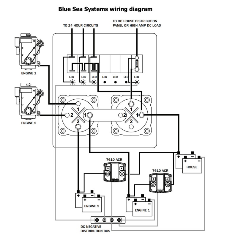
Here's the official diagram for the Blue Sea PN 8689 that is installed on our boat:
| thataway wrote: | | beautiful wiring in the boat and diagram... |
Yeah, not so much anymore...
After cutting away what must have been $20 worth of zip-ties, and having to tear apart the distribution panel just to reveal the wires, under wires, under wires, I can confidently say that all we require is a jar of marinara sauce and the spaghetti bowl inside my battery and transom hatches will be ready for a sprinkle of parm.
I simplified the actual wiring for the diagram below to avoid confusion.
(One of the posts on a dual circuit switch has 6 different wires attached, and the retaining nut just barely gets on the post.)
Here's what I've finally mapped-out on our C-Shalom's nervous system:
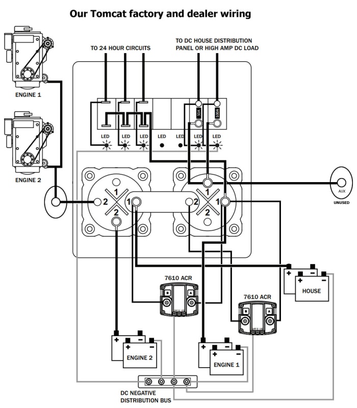
So to sum up, both outboards are tied to each other on a common post that then goes thru one side of the switch to start battery #2.
This is its own circuit that's isolated from both ACRs, start battery#1, house battery, and shore charger, unless switched to the combine position.
Which means we've been drawing enough cranking amps from the single cheapest value-brand battery to start both outboards every time without noticing til now.
On the bright side, that sounds like it would make a pretty impressive advert for the battery mfg. 
On the down side, I'll probably be replacing that poor battery next year... 
| thataway wrote: | | It also looks as if the battery charger leads are going to the ACR, instead of the battery. |
Yeah... I just had to quote that because I know you are way too modest to ever say I told you so. 
I didn't put that on the diagram yet to keep it readable, but you are absolutely right.
Not only are all 3 charger leads going to the ACRs, but one actually loops back on itself instead of going to the battery.
If I was a betting man, I'd have to bet that my TC was wired up on either early Monday morning or late Friday afternoon.
So, before I put this mess back together to get it back to the marina dry store for the week, I'd like to peck the collective c-brat mind.
1) What is the best way to rewire this?
The Blue Sea diagram looks like the most efficient and least complicated way to me.
2) Is there ANY reason I shouldn't completely scrap the factory and dealer wiring to follow the Blue Sea diagram?
3) Where should the shore power charger leads be hooked to the electrical system? (All I know is definitely not where they are now)
4) Since I probably have to disconnect and rewire everything, where would be the best place to wire in a solar charging system and one or two extra house batteries?
Any advice is appreciated.
Last edited by JMacLeod on Mon Oct 29, 2018 12:56 am; edited 1 time in total |
|
| Back to top |
|
|
JMacLeod
Joined: 26 Jun 2018
Posts: 173
City/Region: Stuart
State or Province: FL
C-Dory Year: 2018
C-Dory Model: 255 Tomcat
Vessel Name: C-Shalom
Photos: JMacLeod
|
| Posted: Mon Oct 29, 2018 12:40 am Post subject: |
|
|
Looking at this again,... I don't think the house battery is even going to any loads.
Somebody please correct me if I'm wrong. |
|
| Back to top |
|
|
thataway
Joined: 02 Nov 2003
Posts: 21499
City/Region: Pensacola
State or Province: FL
C-Dory Year: 2007
C-Dory Model: 25 Cruiser
Vessel Name: thataway
Photos: Thataway
|
| Posted: Mon Oct 29, 2018 3:24 pm Post subject: |
|
|
The second diagram is not going to work--at least well.
Why are you not using the Aux charging circuit of the engines?
I would have a start battery for each engine. Then the aux charging circuit to the house batteries.
Too many complicated switches--and VSR... Which are great if you don't have the aux charging circuits.
Battery charger: Pronautic 1220 output: one to each of engine start and one to the house bank. That charger is "smart" and will send proper charge to each of the batteries as needed.
I may be missing something. But try and keep it as simple as possible. If you want a separate bank for an inverter or freezer, etc--then use the VCR / VSR for that bank.
I bought a smaller RV last week--first thing I did was pull out the 2 group 24 house bank and put in 2 AGM Golf carts--that alone doubled my house bank capacity. I'll probably put in a Pronautics 1250 for a charger. The engine has a 200 amp alternator, with dual out puts. one goes to engine start and the other to house bank. I'll monitor use with a Victron 700. Only switches are a monetary solenoid combine and on/off high capacity switch for each bank of batteries. [Start and House]
_________________
Bob Austin
Thataway
Thataway (Ex Seaweed) 2007 25 C Dory May 2018 to Oct. 2021
Thisaway 2006 22' CDory November 2011 to May 2018
Caracal 18 140 Suzuki 2007 to present
Thataway TomCat 255 150 Suzukis June 2006 thru August 2011
C Pelican; 1992, 22 Cruiser, 2002 thru 2006
Frequent Sea; 2003 C D 25, 2007 thru 2009
KA6PKB
Home port: Pensacola FL |
|
| Back to top |
|
|
journey on
Joined: 03 Mar 2005
Posts: 3599
City/Region: Valley Centre
State or Province: CA
C-Dory Year: 2005
C-Dory Model: 25 Cruiser
Vessel Name: journey on
Photos: Journey On
|
| Posted: Mon Oct 29, 2018 3:32 pm Post subject: |
|
|
JMacLeod,
I'm looking at your latest schematic and while I can make a couple of assumptions as to what you have, I'd rather find out for certain. So here are some questions on your diagram.
1. I assume that the ellipse containing a circle with the engine outputs as inputs and leading to the main part of the diagram is just a tie point.
2. You have two blocks in the middle with 1,1,2,2 with various lines leading in and out. Are these blocks switches? If so, how do they make connections, i.e. what are the various states that the switch can provide? R1 to L1 while R2 connects to L2? Does it have a dial or switch levers. I ask, because the switches provided on my C-Dory 25 have a single input and two separate outputs with a rotary dial allowing either 1 or 2 outputs to be connected to the input or both. So I'm unsure as to what you've shown.
Boris |
|
| Back to top |
|
|
JMacLeod
Joined: 26 Jun 2018
Posts: 173
City/Region: Stuart
State or Province: FL
C-Dory Year: 2018
C-Dory Model: 255 Tomcat
Vessel Name: C-Shalom
Photos: JMacLeod
|
| Posted: Mon Oct 29, 2018 5:37 pm Post subject: |
|
|
| journey on wrote: | | 1. I assume that the ellipse containing a circle with the engine outputs as inputs and leading to the main part of the diagram is just a tie point. |
Yes, it's just a post terminal that both engines are tied to before connecting to the switch.
| journey on wrote: | | 2. You have two blocks in the middle with 1,1,2,2 with various lines leading in and out. Are these blocks switches? |
Yes, they're dual circuit switches.
OFF - isolates all four terminals.
ON - connects 1 to 1, 2 to 2.
COMBINE - cross-connects all 4 terminals. |
|
| Back to top |
|
|
JMacLeod
Joined: 26 Jun 2018
Posts: 173
City/Region: Stuart
State or Province: FL
C-Dory Year: 2018
C-Dory Model: 255 Tomcat
Vessel Name: C-Shalom
Photos: JMacLeod
|
| Posted: Mon Oct 29, 2018 6:14 pm Post subject: |
|
|
| thataway wrote: | | The second diagram is not going to work--at least well. |
The only work-around to use the current wiring is to keep both switches in the Combine position at all times.
Not exactly my definition of "works well" either.
| thataway wrote: | | Why are you not using the Aux charging circuit of the engines? |
Dealer didn't include the aux harnesses with the engines.
I may end up purchasing one in the future, but for the time being I'll fix and use the gadgets that it came with.
We still have to purchase some railings, radar arch, radar, VHF antennae, and 2nd chartplotter, so I'd rather shift the boat budget there first.
| thataway wrote: | I would have a start battery for each engine. Then the aux charging circuit to the house batteries.
Too many complicated switches--and VSR... Which are great if you don't have the aux charging circuits.
Battery charger: Pronautic 1220 output: one to each of engine start and one to the house bank. That charger is "smart" and will send proper charge to each of the batteries as needed. |
Yes, between one aux charging harness and the Pronautic, all batteries would charge properly on their own leads without needing the ACRs.
Shame that wasn't considered by the people who put it together.
I still may end up getting the aux harnesses, and eliminating the ACRs to simplify the wiring when we get around to discussing adding the solar and another bank.
For right now, I'm just trying to find out where the proper points are for connecting the leads from the Pronautic to the original Blue Seas diagram.
Btw, which AGM golf cart bats did you buy? |
|
| Back to top |
|
|
thataway
Joined: 02 Nov 2003
Posts: 21499
City/Region: Pensacola
State or Province: FL
C-Dory Year: 2007
C-Dory Model: 25 Cruiser
Vessel Name: thataway
Photos: Thataway
|
| Posted: Mon Oct 29, 2018 9:01 pm Post subject: |
|
|
Here is the issue with the ACR and the Pronautic--which is resolved by using the secondary charging outputs: when there is any voltage over 12.7 volts the batteries combine. This defeats the great feature of the Pronautic which distributes the amount of charge given to each battery depending on its state of charge (determined by the voltage and rate of acceptance of the charge). The ACR is just a "dumb combiner". I doubt that the tech who wired the boat considered that. (or a few other things unfortunately).
I bought the Sam's Club @ $180. Trojans are slightly better, but are $ 90 more per battery. Same weight. A little more capacity claimed for the Trojans. |
|
| Back to top |
|
|
JMacLeod
Joined: 26 Jun 2018
Posts: 173
City/Region: Stuart
State or Province: FL
C-Dory Year: 2018
C-Dory Model: 255 Tomcat
Vessel Name: C-Shalom
Photos: JMacLeod
|
| Posted: Tue Oct 30, 2018 9:24 am Post subject: |
|
|
So, adding an aux harness, eliminating the ACRs/VSRs, and adding a solar panel with controller should end up looking something like this?:
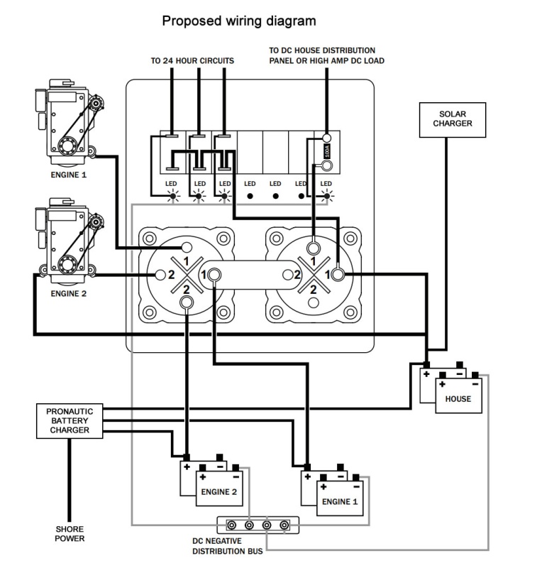
Are there any other adjustments or corrections I need to make to this? |
|
| Back to top |
|
|
thataway
Joined: 02 Nov 2003
Posts: 21499
City/Region: Pensacola
State or Province: FL
C-Dory Year: 2007
C-Dory Model: 25 Cruiser
Vessel Name: thataway
Photos: Thataway
|
| Posted: Tue Oct 30, 2018 10:28 am Post subject: |
|
|
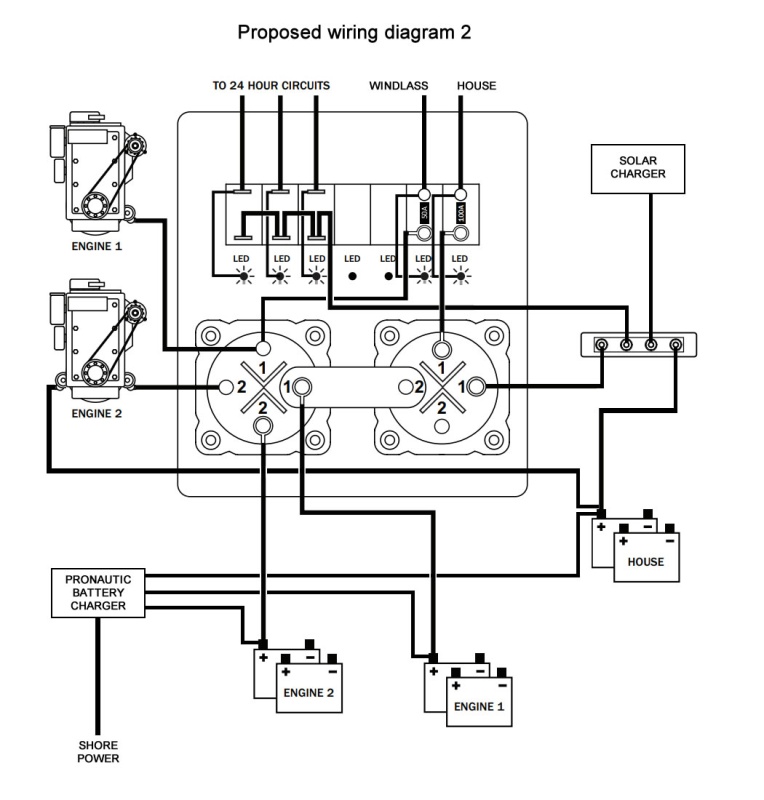
I need to confirm that you have two Blue Seas M "dual circuit plus" 6011; "off / on / combine for 2 batteries?" Thus on "combine" with the left switch (on diagram) you combine the port and Stb engine start batteries. Combine with the right (on diagram), you would combine #1 engine (and its start battery) with the house batteries (if the left switch were sent on "Combine") then both engine start combined with the house.
You will have the Bilge pump # 1, bilge pump #2 and "heater" always "on" from the house bank (no way to shut off. What is the "heater" and why would you want it always wired to house bank?
You will be using that right switch to turn the house load on and off.
You need a ground from the battery charger and ground--I suspect that you left that off for clarity)
Are the two loads off the house bank: house and windlass? Generally the windlass is wired to one of the engine start batteries, with a breaker/switch near the battery, as well as one near the helm. Is the windlass breaker 100 amps? |
|
| Back to top |
|
|
JMacLeod
Joined: 26 Jun 2018
Posts: 173
City/Region: Stuart
State or Province: FL
C-Dory Year: 2018
C-Dory Model: 255 Tomcat
Vessel Name: C-Shalom
Photos: JMacLeod
|
| Posted: Tue Oct 30, 2018 11:56 am Post subject: |
|
|
| thataway wrote: | | I need to confirm that you have two Blue Seas M "dual circuit plus" 6011; "off / on / combine for 2 batteries?" Thus on "combine" with the left switch (on diagram) you combine the port and Stb engine start batteries. Combine with the right (on diagram), you would combine #1 engine (and its start battery) with the house batteries (if the left switch were sent on "Combine") then both engine start combined with the house. |
100% correct.
| thataway wrote: | | You will have the Bilge pump # 1, bilge pump #2 and "heater" always "on" from the house bank (no way to shut off. What is the "heater" and why would you want it always wired to house bank? |
I haven't verified yet, but I assumed that was for the electronic ignition on the stove/heater.
Probably not something we're likely to use that much (if ever) in Florida or the Bahamas, but I'll definitely find out before we join any C-Brats in mountain country.
| thataway wrote: | | Are the two loads off the house bank: house and windlass? Generally the windlass is wired to one of the engine start batteries, with a breaker/switch near the battery, as well as one near the helm. Is the windlass breaker 100 amps? |
There's two breakers at the battery panel labeled House (100A) and DC sub-panel (50A).
The breaker for the Lewmar 700 is 50A at the helm.
With the way the boat came wired, there are currently no loads connected to the house bank at all.
Both engines are wired to start battery #2, and both house breakers are wired to start battery #1.
We didn't realise that single 800 CCA start battery was running the chartplotter, refrigerator, and windlass until we decided to practice anchoring for the first time.
To draw from the house bank now, the DC Main dual circuit switch has to be in the combine position.
The original Blue Sea diagram will rectify that issue, but I need to wrap my head around where to correctly connect the charger leads from both AC and solar.
If I end-up needing to add/cut/modify wires, I can plan it out right the first time and avoid too much wasted copper. |
|
| Back to top |
|
|
thataway
Joined: 02 Nov 2003
Posts: 21499
City/Region: Pensacola
State or Province: FL
C-Dory Year: 2007
C-Dory Model: 25 Cruiser
Vessel Name: thataway
Photos: Thataway
|
| Posted: Tue Oct 30, 2018 12:37 pm Post subject: |
|
|
50 amps is enough for the "house" (unless you have an inverter--and a small inverter may have been the intent of the 100 amp breaker??) Bit for inverters you need heavy wiring--so even giving the benefit of the doubt--probably not correct,
You want a 50 or 60 breaker or fuse close to the engine start battery which you will use for the windlass. Why engine start? You want to start the engine and drive the boat to over the anchor--so the engine is already running and keeping the battery voltage up. You don't want the large draw of the windlass on the electronics (house) because low voltage may cause them to drop out, as you pull the anchor. ABYC specifies a breaker within 7" of the battery for unsupported cables.
OK on the "Wallas Stove" being the "heater" But both Wallas and bilge pump manufacturers suggest that these loads not go thru a switch.--what is happening here, although that part of the circuit is not being switched--The voltage may be drawn down by high house loads, and you are making a switch terminal into a bus bar (or single point terminus.) .
I would make one connection, close to the battery, as a terminal point or buss bar--to that you put "house load", Wallas stove, two bilge pumps, and the output of controller for solar panels. |
|
| Back to top |
|
|
thataway
Joined: 02 Nov 2003
Posts: 21499
City/Region: Pensacola
State or Province: FL
C-Dory Year: 2007
C-Dory Model: 25 Cruiser
Vessel Name: thataway
Photos: Thataway
|
| Posted: Tue Oct 30, 2018 2:33 pm Post subject: |
|
|
| To clarify that one point may be a buss bar--often there are two large terminals and multiple small terminals. All of these should be coated with marine grade dielectric grease to prevent corrosion at the terminals--and exposed part of wire connector--I like to use thermal activated adhesive lined crimp fittings anywhere near the batteries (best everywhere). |
|
| Back to top |
|
|
JMacLeod
Joined: 26 Jun 2018
Posts: 173
City/Region: Stuart
State or Province: FL
C-Dory Year: 2018
C-Dory Model: 255 Tomcat
Vessel Name: C-Shalom
Photos: JMacLeod
|
| Posted: Tue Oct 30, 2018 4:09 pm Post subject: |
|
|
Something along these lines?
 |
|
| Back to top |
|
|
thataway
Joined: 02 Nov 2003
Posts: 21499
City/Region: Pensacola
State or Province: FL
C-Dory Year: 2007
C-Dory Model: 25 Cruiser
Vessel Name: thataway
Photos: Thataway
|
| Posted: Tue Oct 30, 2018 5:18 pm Post subject: |
|
|
| Looks good to me--but run thru scenarios in your head where it could be wrong... |
|
| Back to top |
|
|
|
|
You cannot post new topics in this forum
You cannot reply to topics in this forum
You cannot edit your posts in this forum
You cannot delete your posts in this forum
You cannot vote in polls in this forum
You cannot attach files in this forum
You cannot download files in this forum
|
|
 Search
 Private Messages
 Profile
 Log in
 Register
 Help
Help
