| View previous topic :: View next topic |
| Author |
Message |
thataway
Joined: 02 Nov 2003
Posts: 20810
City/Region: Pensacola
State or Province: FL
C-Dory Year: 2007
C-Dory Model: 25 Cruiser
Vessel Name: thataway
Photos: Thataway
|
 Posted: Thu Mar 15, 2012 1:35 pm Post subject: How to properly solder a PL 259 connector (VHF antenna) Posted: Thu Mar 15, 2012 1:35 pm Post subject: How to properly solder a PL 259 connector (VHF antenna) |
 |
|
There are some tricks to soldering a PL 259 connector, which I want to share with the C Brats.
Tools: Bench or heavy machinist vise, 40 watt pencil type of soldering iron, 6" mill bastard file, knife, good diagonal wire cutters.
PL 259--get a quality connector. You want the coax adaptor sized for the cable you are using. The coax connector should be grass silver plated, and the center pin should be brass, un plated.
Technique. Set the Adaptor in the vise: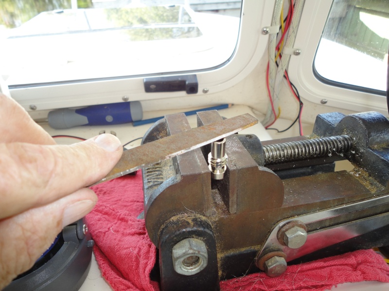
Use the 6" Mill file to remove any plating on the top of the adaptor, and scrape out the center of the adaptor with the file end, and round the outer upper edges of the adaptor.
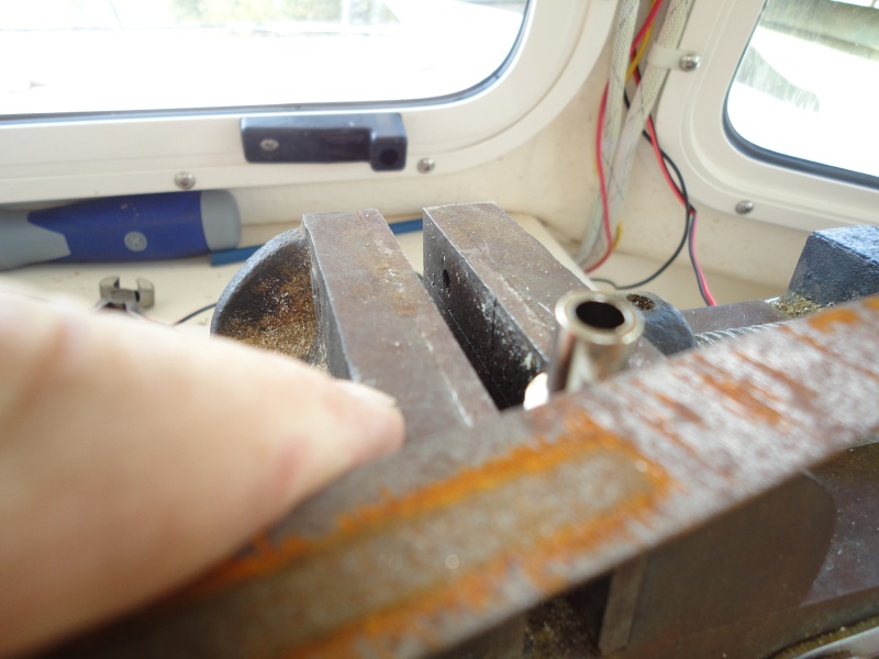
Then use the file to remove a band of plating around the adaptor where the holes of the main body will line up.
Tin the top of the center adaptor with the 40 watt soldering iron--then put a small band of solder around the adaptor where the holes will line up--the area you filed.
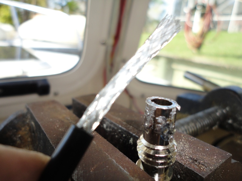
Then put the braid up thru the center of the adaptor, work the braid back down around the top of the adaptor and sweat solder the braid to the top of the adaptor
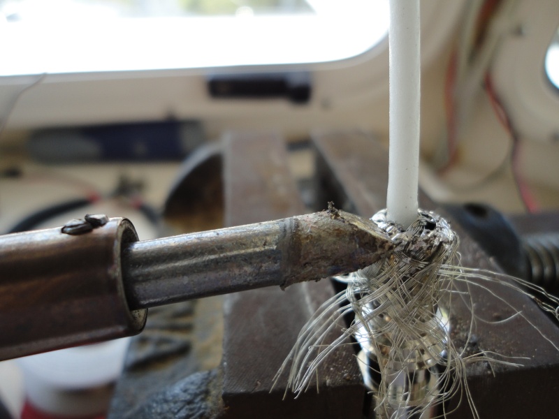
Trim off the excess braid, and clean up the top with the soldering iron to bring a bit of solder down into the body of the adaptor and around where the holes will be.
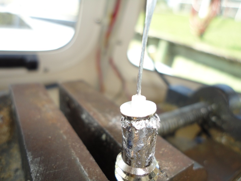
In the above picture a metal washer, and then a teflon washer are put around the 1/4" of inner conductor insulation.
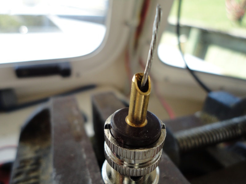
Next the body of the PL 259 is placed over the adaptor, and solder applied to the center conductor, allowing it to wick down the conductor and to the inside of the brass center pin--you do not have to heat the brass center pin until the solder has flowed into it--and then heat only the very top--applying some final solder to seal the end of the center pin.
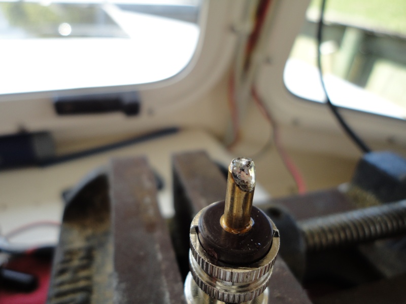
The center conductor is cut flush with the center pin end and any excess solder is filed away if necessary.
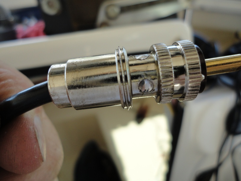
Finally the soldering iron is applied to the holes of the body after it has been screwed down tight on the center adaptor. You don't put solder on the iron or body, but in the hole if necessary
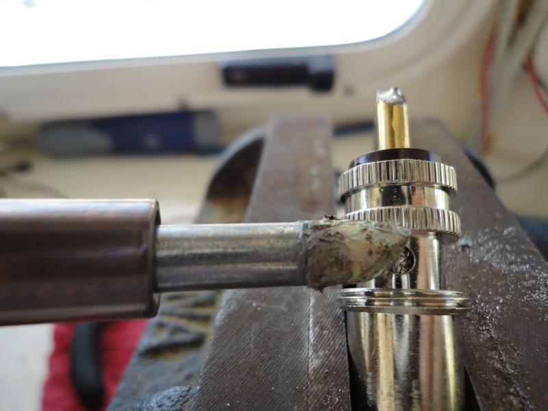
The final result shows that the solder is slightly concave in the body holes, and has flowed well between the body and the adaptor.
OK for those who have hung in so far, here are the differences from the "usual" technique. First we use the vise as a heat sink, the adaptor is clamped in the vise at almost every step, and this helps to avoid heat damage to the insulation of the cable.
Second, we do not pull the braid down over the adaptor, so it is soldered in the holds. This is not necessary, since the braid is soldered at the top of the adaptor, and gives a much better joint.
Third, we use a low heat iron, not a 140 watt gun. This also helps to avoid any damage to insulation.
Fourth, we avoid excess solder on the center pin and on the body of the PL259.
_________________
Bob Austin
Thataway
Thataway (Ex Seaweed) 2007 25 C Dory May 2018 to Oct. 2021
Thisaway 2006 22' CDory November 2011 to May 2018
Caracal 18 140 Suzuki 2007 to present
Thataway TomCat 255 150 Suzukis June 2006 thru August 2011
C Pelican; 1992, 22 Cruiser, 2002 thru 2006
Frequent Sea; 2003 C D 25, 2007 thru 2009
KA6PKB
Home port: Pensacola FL |
|
| Back to top |
|
 |
NORO LIM
Joined: 24 Apr 2008
Posts: 875
City/Region: Olympia
State or Province: WA
C-Dory Year: 2006
C-Dory Model: 23 Venture
Vessel Name: NORO LIM (sold 12/12/14)
Photos: NORO LIM
|
| Posted: Thu Mar 15, 2012 2:15 pm Post subject: |
|
|
Excellent! (as usual) Makes me want to go disassemble every connector I have and start over. Thank you?
_________________
Bill, Formerly on NORO LIM
2001 CD 16, 2001-2006
2006 CC 23, 2006-2014 |
|
| Back to top |
|
|
potter water
Joined: 12 Apr 2011
Posts: 1076
City/Region: Logan
State or Province: UT
C-Dory Year: 1997
C-Dory Model: R-21 Tug
Vessel Name: Poopsy
Photos: Still C-razy
|
| Posted: Thu Mar 15, 2012 3:02 pm Post subject: |
|
|
Very nice presentation.
The PL259's are designed to be properly assembled without many of the steps you've done with the filing and so on.
I've assembled hundreds of these in the television station business and in the nuclear reactor business. I never did any of these steps and had no problems. Those were days when speed was of the essence though.
You are clearly doing the belt and suspender method and are to be commended for the patience and the end product.
I'd like to see your approach to BNC's. Those are tougher than the 259 to get right.
Good job.
It would be nice if others on the board would provide this really substantive photo documentation on their projects. We could all learn a lot.
_________________
You can tell a man his wife is ugly, but never ever criticize his dog, his gun, his truck or his boat.
Never let ignorance interfere with an opportunity to state a knowledgeable opinion
Testosterone Tales-Amazon.com
2006 C-Dory 22 Cruiser 2008-2014
1997 Ranger Tug 21 Classic 2016
KG7RC |
|
| Back to top |
|
|
thataway
Joined: 02 Nov 2003
Posts: 20810
City/Region: Pensacola
State or Province: FL
C-Dory Year: 2007
C-Dory Model: 25 Cruiser
Vessel Name: thataway
Photos: Thataway
|
| Posted: Thu Mar 15, 2012 3:32 pm Post subject: |
|
|
An improperly assembled PL 259 is one of the most common problems with marine VHF radios--and included in that I mean one which has corrosion problems. Doing these steps essentially assures that there will be minimal corrosion problems, since there is a good mechanical/electrical connection.
For example on the Nordhavn Atlantic Rally, some some of the boats were "seeing" over 40 miles in their AIS--some only 10 miles. It turned out the difference was improperly installed PL 259's--many professionally installed. |
|
| Back to top |
|
|
Matt Gurnsey
Dealer
Joined: 11 Nov 2008
Posts: 1532
City/Region: Port Orchard
State or Province: WA
Photos: Kitsap Marina
|
| Posted: Thu Mar 15, 2012 5:29 pm Post subject: |
|
|
Nice tutorial.
Bad PL259's are probably the number one problem we see with VHF radios.
Shakespeare's solderless Centerpin connectors are a great alternative if you're not up to the task of soldering, and make a great emergency back up connector- Simply cut the wire square and install.
_________________
Matt Gurnsey
Kitsap Marina
www.kitsapmarina.com
360-895-2193
(888) 293-7991 |
|
| Back to top |
|
|
Garage Guy
Joined: 03 Jan 2012
Posts: 2
City/Region: Gabriola
State or Province: BC
|
| Posted: Thu Mar 15, 2012 5:45 pm Post subject: Re: How to properly solder a PL 259 connector (VHF antenna) |
|
|
| thataway wrote: | | The coax connector should be grass silver plated, and the center pin should be brass, un plated. |
From the pictures, that looks more like nickel plating to me, not silver. Anyway, if it is silver, I'm wondering why file it off? Nothing solders better than silver. And I hope the center pin gold plated, not bare brass! (Brass isn't very corrosion resistant...)
I used to solder all my connectors, but after having worked on aviation electronics for a few years, where nothing is soldered and everything is crimped, I've switched over to crimping. The downside is that a good crimper, with the correct dies, is expensive. The main upsides are better vibration resistance, and not having to worry about melting any insulation. If you can justify the crimper cost, or borrow the right crimper, I'm now convinced this the way to go.
(Just my 2 cents..!) |
|
| Back to top |
|
|
localboy
Joined: 30 Sep 2006
Posts: 4656
City/Region: Lake Stevens via Honolulu
State or Province: WA
C-Dory Year: 2007
C-Dory Model: 25 Cruiser
Vessel Name: 'Au Kai (Ocean Traveler)
Photos: 'AU KAI
|
| Posted: Thu Mar 15, 2012 5:45 pm Post subject: |
|
|
| NORO LIM wrote: | | Excellent! (as usual) Makes me want to go disassemble every connector I have and start over. Thank you? |
Ditto. I used a butane pen and melted it in all the holes. But I didn't remove any of the plating.
_________________
"We can go over there...behind the 'little one'....."
Wife to her husband pointing @ us...from the bow of their 50-footer; Prideaux Haven 2013 |
|
| Back to top |
|
|
thataway
Joined: 02 Nov 2003
Posts: 20810
City/Region: Pensacola
State or Province: FL
C-Dory Year: 2007
C-Dory Model: 25 Cruiser
Vessel Name: thataway
Photos: Thataway
|
| Posted: Thu Mar 15, 2012 7:10 pm Post subject: |
|
|
The reason for filing is assumption that the adaptor is nickel or chrome (it happens on cheap stuff) plated. I would hope that the center pin is gold plated--but in todays world I would not guarantee that. This is a good reason to use an anti corrosion grease when installing the PL 259 on the radio (and under all connections you make on terminal blocks etc.
Agree if we knew that this was silver plated, then the filing off would not be necessary.
I have seen a lot of problems with the Shakespeare's solder less Centerpin, the reasons are that there is not a solid contact, and the penetration of the shield is variable. Also this type of connector is subject to corrosion. It may be OK in a pinch, but a good solder job is far better.
A good professional crimped PL 259 is excellent. However, one of the problems is that there are a number of different sized cables used for VHF antennas, and thus not only does one have to buy several high quality crimpers but prep tools to do it efficiently. The cost would be at least in the $250 to $300 range. I'll have to confess I have a number of different crimp tools, I have used for various coax cables thru the years, and I have found better results with the old soldering iron....
However for most electrical connections I use a quality two stage crimper. The exception is the very fine wires which I will be using for the GPS to radio connection--those I will solder and adhesive heat shrink. I suspect that the average airplane has far more vibration and hours of use than our C Dories. But that is a good argument. On the other hand I believe that solder is still used on circuit boards--and there are a lot of those in use many places. |
|
| Back to top |
|
|
journey on
Joined: 03 Mar 2005
Posts: 3595
City/Region: Valley Centre
State or Province: CA
C-Dory Year: 2005
C-Dory Model: 25 Cruiser
Vessel Name: journey on
Photos: Journey On
|
| Posted: Sat Mar 17, 2012 3:10 pm Post subject: |
|
|
Interesting (to me) that crimping is mentioned as a reliable method of making connections.
On spacecraft all electrical connections are crimped. I innocently asked why they left soldering, and after the 2 hour lecture, the answer was reliability. One can make a repeatable, testable crimp, whilst soldering required skill and wasn't as easily testable.
Of course solder is still used on PC boards, etc. but harnesses are crimped to their pins.
I'm afraid I still use the crimp method for RF connectors as well as electrical ones, too. I figure the RF frequencies are in the megaHz, so close counts. Unless there's corrosion, when all bets are off.
I just noticed that Wikipedia has this statement on silver plating:
| Quote: | Silver plating
For applications in electronics, silver is sometimes used for plating copper, as its electrical resistance is lower (see Resistivity of various materials); more so at higher frequencies due to the skin effect....
Care should be used for parts exposed to high humidity environments. When the silver layer is porous or contains cracks, the underlying copper undergoes rapid galvanic corrosion, flaking off the plating and exposing the copper itself; a process known as red plague. |
Boris |
|
| Back to top |
|
|
potter water
Joined: 12 Apr 2011
Posts: 1076
City/Region: Logan
State or Province: UT
C-Dory Year: 1997
C-Dory Model: R-21 Tug
Vessel Name: Poopsy
Photos: Still C-razy
|
| Posted: Sat Mar 17, 2012 6:48 pm Post subject: |
|
|
| In the earlier decades of space flight when we were just getting into orbiting craft and deep space craft that would have missions of many years or even decades, some failures were attributed to what are called dendritious material. Those were materials like lead and cadmium that would develop little dendrites or hairs that would grow and cause shorts in low power circuitry at the connectors. That was another reason that crimping, particularly in densely packed connectors, took over as the best way to do things. And, yes, if a tool is used to crimp, then the crimp can be done by lower level folks more reliably than solder. Dendrites can also grow between closely spaced parts on a printed board, but those boards are almost all POTTED to keep the parts secure and to block dendrite growth. None our applications as boat owners really requires expensive crimping tools for wiring. Solder is just fine. Aircraft and spacecraft have entirely different and unique environment that requires a belt and suspenders approach. (read as much more expensive). |
|
| Back to top |
|
|
hardee
Joined: 30 Oct 2006
Posts: 12632
City/Region: Sequim
State or Province: WA
C-Dory Year: 2005
C-Dory Model: 22 Cruiser
Vessel Name: Sleepy-C
Photos: SleepyC
|
| Posted: Sun Mar 18, 2012 2:32 pm Post subject: |
|
|
Dr Bob,
Thanks for the fine photo and description essay. I agree, we could use more of that type of posting around here. Would be nice to have those type of posts in an easily accessible file. Maybe they are already easy for some but I have spent more time than I like to admit looking for things I saw here once and then tried to go back and find when I needed them.
Thanks all,
Harvey
SleepyC 
_________________
Though in our sleep we are not conscious of our activity or surroundings, we should not, in our wakefulness, be unconscious of our sleep. |
|
| Back to top |
|
|
localboy
Joined: 30 Sep 2006
Posts: 4656
City/Region: Lake Stevens via Honolulu
State or Province: WA
C-Dory Year: 2007
C-Dory Model: 25 Cruiser
Vessel Name: 'Au Kai (Ocean Traveler)
Photos: 'AU KAI
|
| Posted: Sun Apr 13, 2014 5:42 pm Post subject: |
|
|
Did this today with our second antenna; it's a new install. Followed the instructions. Easier said than done. My soldering looks nothing like Dr Bob's. Mine is less. uh, perfect......  |
|
| Back to top |
|
|
Sea Angel
Joined: 29 Dec 2003
Posts: 736
City/Region: Virginia Beach, VA
State or Province: VA
Photos: Sea Angel
|
| Posted: Sun Apr 13, 2014 6:41 pm Post subject: |
|
|
Over the years I have also invested in sets of crimp tools for BNC, 50 and 75 ohm impedances and the PL259 UHF connector all for the RG6, RG8X, RG8/U, RG58 and RG59 cables.
I mention this to show that there are individual crimp tools and crimp tool sets with interchangeable jaws and stripper/cutters available for the PL259 series for most of the common cables available.
Please be sure match the cable, crimp and connector type needed to money, time and reliability.
I wish I had a nickel for all the connectors and cables I had to assemble in the Navy and in TV broadcasting; especially when we transitioned from analog to digital TV. There was a time that soldering the connectors at the TV station was done and it was not missed when crimping arrived.
If you do solder, please be sure you have the correct adaptor sized for the cable used with PL259.
Bob, nice teach.......
As had been said, just my 2 cents worth.
Art
_________________
Art ka1rx
CBRAT #208
2005 CD25 #075 SEA ANGEL (SOLD)
USCGAUX (RET), USN(RET)
Broadcast TV ENG(RET)
ka1rx@verizon.net
SKYPE: Art.Bartlett4 |
|
| Back to top |
|
|
localboy
Joined: 30 Sep 2006
Posts: 4656
City/Region: Lake Stevens via Honolulu
State or Province: WA
C-Dory Year: 2007
C-Dory Model: 25 Cruiser
Vessel Name: 'Au Kai (Ocean Traveler)
Photos: 'AU KAI
|
| Posted: Sun Apr 13, 2014 8:05 pm Post subject: |
|
|
| It worked. Everything appears solid and the solder was sucked in to the connector. I used a gold Shakespeare connector and the solder appeared to not want to adhere at times. I kept at it, though. It's just an aesthetics thing to me; I want to do things correctly the FIRST time and dislike messy work. No one will see it though. As long as it works ....I"ll be happy. |
|
| Back to top |
|
|
Robert H. Wilkinson
Joined: 26 Jan 2011
Posts: 1234
City/Region: Port Ryerse
State or Province: ON
Vessel Name: Romakeme IV
Photos: Romakeme IV
|
| Posted: Mon Apr 14, 2014 6:38 pm Post subject: |
|
|
Excellent write up Bob. Thanks for sharing that.
Just a note regarding soldering. A solder only connection is not recommended on boats. The reason for this is that at the point where the stranded wire is soldered it in effect becomes solid wire. This then becomes susceptible to all the problems associated with solid wire when subjected to vibration and any movement. If connections are soldered they must be supported beyond the solder with adhesive filled heat shrink. Also a small loop can be made in the wire and held with cable ties so that any stress will pull on the slack provided by the loop as opposed to straining the connection itself.
In Bobs example the wire is supported by the connector mechanically. This rule applies mainly for example when joining 2 wires together or soldering wires to the terminals of a toggle switch, etc.
Regards, Rob
_________________
Talk to me and I will listen-- but if its not about boats or fishing all I will hear is bla,bla,bla,yada,yada,zzzzzzzz |
|
| Back to top |
|
|
|
|
You cannot post new topics in this forum
You cannot reply to topics in this forum
You cannot edit your posts in this forum
You cannot delete your posts in this forum
You cannot vote in polls in this forum
You cannot attach files in this forum
You cannot download files in this forum
|
|
 Search
 Private Messages
 Profile
 Log in
 Register
 Help
Help
