| View previous topic :: View next topic |
| Author |
Message |
smckean (Tosca)
Joined: 18 Jan 2014
Posts: 975
City/Region: Guemes Island (Anacortes)
State or Province: WA
C-Dory Year: 2005
C-Dory Model: 25 Cruiser
Vessel Name: Tosca
Photos: Tosca
|
 Posted: Wed Jul 14, 2021 2:56 pm Post subject: How to wire a VSR to allow disabling for boat storage Posted: Wed Jul 14, 2021 2:56 pm Post subject: How to wire a VSR to allow disabling for boat storage |
 |
|
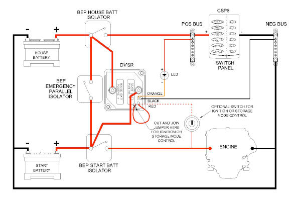
I'm about to install a new BEP 716-Sq-140A-Dvsr cluster of switches and VSR. The VSR has a special loop of wire that can be cut (see image below) so that one can install a toggle switch which disables the VSR totally. I want to do this so that when the boat is in storage, and on my dual output charger, each battery will be charged independently according to the charger's absorption/float profile. To have the batteries independent, I need to have the VSR disabled. This on/off switch also provides the advantage of no amperage draw by the VSR when the boat is stored.
Looking at the diagram it seems to me I could connect the cut red wire directly to the engine side of the start battery switch instead of going thru a stand alone toggle switch. If I did that, it seems to me that the VSR would be enabled any time I have the start battery switch in the "on" position, and disabled if the start battery switch were in the "off" position. Since I must have the start battery switch on when I run the engine, and I always turn it off when the engine isn't running (except at anchor), this would give me what I want painlessly in the sense that the VSR would operate whenever the start battery switch was on, and not operate with the start battery switch off.
Can anyone see why this wouldn't work, or if there is some downside I've missed?
P.S. Another way to look at this setup is: I want the VSR to combine when the source of the charging current is the alternator, and to not combine if the source is my charger.
_________________
Sandy McKean
Purchased Tosca in 2014
Re-powered to Yammi 200 in 2015 |
|
| Back to top |
|
 |
thataway
Joined: 02 Nov 2003
Posts: 20803
City/Region: Pensacola
State or Province: FL
C-Dory Year: 2007
C-Dory Model: 25 Cruiser
Vessel Name: thataway
Photos: Thataway
|
| Posted: Fri Jul 16, 2021 11:47 am Post subject: |
|
|
The manual states:
| Quote: | Optional Ignition Control/Storage Mode (red wire):
Cut end of the red looped wire ( end closest to red dotted Start Batt Positive + stud) where it joins the PCB/potting, connect the remain- ing tail to the ignition terminal on the engine ignition/start switch. With this feature selected the DVSR will only operate when the ignition key is in the ON position (i.e. engine running). With the ignition switch OFF, current draw of the DVSR will be zero Amps.
|
If I understand the way the cluster works, you should be good to go. The manual calls for either the ignition switch, or as you noted a toggle switch.
_________________
Bob Austin
Thataway
Thataway (Ex Seaweed) 2007 25 C Dory May 2018 to Oct. 2021
Thisaway 2006 22' CDory November 2011 to May 2018
Caracal 18 140 Suzuki 2007 to present
Thataway TomCat 255 150 Suzukis June 2006 thru August 2011
C Pelican; 1992, 22 Cruiser, 2002 thru 2006
Frequent Sea; 2003 C D 25, 2007 thru 2009
KA6PKB
Home port: Pensacola FL |
|
| Back to top |
|
|
smckean (Tosca)
Joined: 18 Jan 2014
Posts: 975
City/Region: Guemes Island (Anacortes)
State or Province: WA
C-Dory Year: 2005
C-Dory Model: 25 Cruiser
Vessel Name: Tosca
Photos: Tosca
|
| Posted: Fri Jul 16, 2021 1:39 pm Post subject: |
|
|
Well, my plan is to do something a bit different that either of the manufacturer options you mention. I don't plan to use either a toggle switch or wire the VSR to the ignition switch. That's why I am a bit unsure about my plan. It seems to me that wiring that red wire to the engine side of the starter battery switch accomplishes the same thing (which may be what you are implying), but perhaps there are other consequences that flow from doing it in this "non recommended" way that I am blind to.
Well, I'm just going to do it. I feel pretty confident that my plan will work. Getting operating power to the VSR via the engine side of the start battery switch allows me to keep the house and start batteries separate while charging in boat storage, and not have to worry about yet another switch. (The ignition option saves me that worry too, but I don't want to have to run a wire from the stern lazerette to the helm.) |
|
| Back to top |
|
|
Ferg
Joined: 18 Jun 2015
Posts: 187
City/Region: Oak Island
State or Province: NC
C-Dory Year: 2008
C-Dory Model: 25 Cruiser
Vessel Name: Here & Now
Photos: Here & Now
|
| Posted: Fri Jul 16, 2021 2:53 pm Post subject: |
|
|
| If you wire it to the engine side of the start battery, and the start battery has high enough residual voltage (from the last charge) to initiate paralleling, youll be using both banks to start the engine. |
|
| Back to top |
|
|
smckean (Tosca)
Joined: 18 Jan 2014
Posts: 975
City/Region: Guemes Island (Anacortes)
State or Province: WA
C-Dory Year: 2005
C-Dory Model: 25 Cruiser
Vessel Name: Tosca
Photos: Tosca
|
| Posted: Fri Jul 16, 2021 3:35 pm Post subject: |
|
|
Ferg,
I think you are misunderstanding what I'm trying to do. I assume you understand that when you say "wire it to the engine side of the start battery" that is not what I'm doing. What I'm talking about correctly said is "wire it to the engine side of the start battery switch".
My scheme has nothing to do with wiring the large, high amp cables that come from the batteries to the switches, or from the switches to the distribution blocks or devices. I am only talking about how to connect the VSR to a source to supply the VSR's operating power. That operating power is supplied in the factory unit via that little red wire in the diagram above. I presume that in the factory version that red wire is connected to the posts coming from either or both the batteries. When I cut that little red wire, the VCR simply does not operate at all unless I supply a positive 12v connection. It is that operating power connection that I am talking about connecting to the engine side of the start battery switch.
The "problem" you mention would be true of any VSR installation. |
|
| Back to top |
|
|
Ferg
Joined: 18 Jun 2015
Posts: 187
City/Region: Oak Island
State or Province: NC
C-Dory Year: 2008
C-Dory Model: 25 Cruiser
Vessel Name: Here & Now
Photos: Here & Now
|
| Posted: Fri Jul 16, 2021 4:09 pm Post subject: |
|
|
| I did understand thats what you meant Sandy. As you know, I did the switch, which completely isolates the VSR, and takes out any possibility of paralleling when starting the engine. |
|
| Back to top |
|
|
smckean (Tosca)
Joined: 18 Jan 2014
Posts: 975
City/Region: Guemes Island (Anacortes)
State or Province: WA
C-Dory Year: 2005
C-Dory Model: 25 Cruiser
Vessel Name: Tosca
Photos: Tosca
|
| Posted: Tue Jul 20, 2021 5:01 pm Post subject: |
|
|
Just to close the loop on this thread.......
I ended up wiring the new 716 switch/VSR cluster as per the manufacturer's recommendations. Turns out there appears to be a great deal of misunderstanding regarding how a VSRs (ACRs) work, and especially how multi-output chargers work. I spent a lot of time researching and learned a lot. Bottom line was that a multi-output charger provides no benefit over a single output charger with a VSR. Once I understood that, the whole reason for why I wanted to do a modified install disappeared.
At some point I will likely post a new thread on C-Brats spelling out what I learned.....one of the biggest items is the common misconception (I certainly had it) that multi-output chargers use independent charge profiles for each output. Almost all the chargers out there do not do this....although their marketing text is designed to make you think so. |
|
| Back to top |
|
|
|
 Search
 Private Messages
 Profile
 Log in
 Register
 Help
Help
