| View previous topic :: View next topic |
| Author |
Message |
JMacLeod
Joined: 26 Jun 2018
Posts: 173
City/Region: Stuart
State or Province: FL
C-Dory Year: 2018
C-Dory Model: 255 Tomcat
Vessel Name: C-Shalom
Photos: JMacLeod
|
 Posted: Fri Oct 05, 2018 7:36 am Post subject: Latest TC255 wiring diagram? Posted: Fri Oct 05, 2018 7:36 am Post subject: Latest TC255 wiring diagram? |
 |
|
I'm heading down to the boat today for some electrical troubleshooting and battery/electronic/wire planning.
I found the 2008 schematic uploaded to the docs (Thanks, Captains Cat), but was wondering if there are any newer diagrams floating around? |
|
| Back to top |
|
 |
Sea Wolf
Joined: 01 Nov 2003
Posts: 8650
City/Region: Redding
State or Province: CA
C-Dory Year: 1987
C-Dory Model: 22 Cruiser
Vessel Name: Sea Wolf
Photos: Sea Wolf
|
| Posted: Fri Oct 05, 2018 9:22 am Post subject: |
|
|
As you no doubt have figured out, very few wiring diagrams exist for C-Dorys in general, partially because of the many different manufacturers that have built the boats over the years, partially because of the variations within the production runs of the individual builders, and partially because different years saw different equipment available at the time of manufacture. What is more, much of the final rigging is done by the individual dealer who sells the boat and adds the engine(s), electronics, and other accessories.
However, since yours is a 2018 model, why not just ask the present manufacturer if they have a diagram you can get a copy of ?
If you get one, be sure to post a copy of it here.
Good Luck!
Joe.  
_________________
Sea Wolf, C-Brat #31
Lake Shasta, California
  
"Most of my money I spent on boats and women. The rest I squandered'. " -Annonymous |
|
| Back to top |
|
|
JMacLeod
Joined: 26 Jun 2018
Posts: 173
City/Region: Stuart
State or Province: FL
C-Dory Year: 2018
C-Dory Model: 255 Tomcat
Vessel Name: C-Shalom
Photos: JMacLeod
|
| Posted: Fri Oct 05, 2018 9:57 am Post subject: |
|
|
| Sea Wolf wrote: | As you no doubt have figured out,...
...However, since yours is a 2018 model, why not just ask the present manufacturer if they have a diagram you can get a copy of ?
If you get one, be sure to post a copy of it here. |
Thanks, Joe.
I requested a copy from the dealer yesterday and already sent a request via the mfg website as a backup this morning, so hopefully I'll get an answer up or down before the end of business today.
If they send me anything I'll definitely upload a copy to the archives. |
|
| Back to top |
|
|
thataway
Joined: 02 Nov 2003
Posts: 20988
City/Region: Pensacola
State or Province: FL
C-Dory Year: 2007
C-Dory Model: 25 Cruiser
Vessel Name: thataway
Photos: Thataway
|
| Posted: Fri Oct 05, 2018 11:32 am Post subject: |
|
|
I have found that factory wiring was inconsistent thru the years. The wiring is simple and fairly easy to trace. The first thing to do is label each and every circuit at the fuse origin and the terminus no matter what a diagram may show. It is rare that color coding or marked wires are found in any C dory. I use a standard brother labeler and wrap the labels around the wires.
_________________
Bob Austin
Thataway
Thataway (Ex Seaweed) 2007 25 C Dory May 2018 to Oct. 2021
Thisaway 2006 22' CDory November 2011 to May 2018
Caracal 18 140 Suzuki 2007 to present
Thataway TomCat 255 150 Suzukis June 2006 thru August 2011
C Pelican; 1992, 22 Cruiser, 2002 thru 2006
Frequent Sea; 2003 C D 25, 2007 thru 2009
KA6PKB
Home port: Pensacola FL |
|
| Back to top |
|
|
JMacLeod
Joined: 26 Jun 2018
Posts: 173
City/Region: Stuart
State or Province: FL
C-Dory Year: 2018
C-Dory Model: 255 Tomcat
Vessel Name: C-Shalom
Photos: JMacLeod
|
| Posted: Fri Oct 05, 2018 12:38 pm Post subject: |
|
|
Thanks, Bob, that's pretty much as I figured.
Excellent suggestion. Those P-Touch labelers are great for cable management.
The boat is kept 3 hours away, and I'll get some "hands-on" time to trace and flag wires tomorrow and Sunday before heading back home.
The diagram is just a navigation aid while I'm crawling around the boat, as well as something I can use to plan out any modifications/additions while I'm away from the boat.
The 2008 diagram should be sufficient for purpose if there's not a more up to date version available. |
|
| Back to top |
|
|
gulfcoast john
Joined: 14 Dec 2012
Posts: 1001
City/Region: PENSACOLA
State or Province: FL
C-Dory Year: 2010
C-Dory Model: 255 Tomcat
Vessel Name: Cat O' Mine
Photos: CAT O' MINE
|
| Posted: Fri Oct 05, 2018 9:17 pm Post subject: wiring |
|
|
Hi John!
Youll figure it out.
In my simpleton mind, there are only 3 legs to the 12v system:
3 batteries (stbd eng, House, port eng) to 2 rotary battery switches (Engines, House) which determine where the 12v energy goes and whether any 2 banks will be Combined.
Bilge pumps, CO detectors, and (possibly) stereo memory will be wired direct to batteries, prior to any switches.
When shorepower and the 110v Battery Charger are both ON, all 3 batteries will get charged via direct wiring from the charger to the + battery terminals and Neg to the Common Ground Bus mounted on the transom which ultimately is the engine ground into the water.
When you go out on the water, the two Engine batteries will be charged by the alternators in their engine (P&S), but the House battery wont be charged by anything at all once disconnected from shorepower (unless you change the House rotary switch to Combined, which in my boat only combines it with Port engine battery, not the starboard one, so if you hook up a VSR voltage sensitive relay $79 gizmo like I did to the stbd eng battery and House battery nothing gets charged at all while underway on the water). I discovered this after 5 years while running the St John river with only one engine on, the other down but off, and noting the voltages on the helm VDC meter. No wonder the House Combined switch still resulted in running down my House battery after a day of running electronics, the fridge on 12V and the windlass, a real amp hog. 12.5v is a resting charged battery, 13.0v or above means something somewhere is charging, and 12.22v is the 50% discharged danger zone
combine or charge em.
From the rotary battery selector switch, two huge 12V Pos cables will run toward the helm on the stbd side, one to the helm bus under the steering station which powers all DC items forward of the throttles, and the other to the windlass and its solenoid controller.
One relatively small wiring harness from the engines to the binnacle/throttles comes from the engines and from there to any engine instruments on the panel. (An independent blue wire from the Nav light switch lights pertinent instrument gauges etc when underway at night from the Helm 12v bus, though the instrument reading itself is from its engine via the Engine Harness).
You can set up your Garmin 7612 to show its Unit 12vDC voltage and set alarms for low voltage (12.22VDC is a 50% discharge, under 12.2v is not ideal).
Maybe this is the page:
Setting Up the Battery Management Page
1. Select A/V, Gauges, Controls > Battery Management > Menu > Edit Devices.
2. Select an item.
3. Select Device, and select an item from the list.
4. If necessary, select Name, enter a name for this device, and select Done.
5. If necessary, select Change Icon, select a new symbol, and select Done.
6. Repeat steps 2 through 5 for each device.
Sorry you bumped the cowling.
On Cat O Mine, the Definition of A Good Boating Day is:
-Total damages under $1,000
-No one is seriously injured or killed
We had a really violent lift in the Joe Wheeler lock on the Tennessee river that blasted the bow sponsons away from the lock wall and resulted in an engine cowling getting scraped and gouged up the 90 feet or so of rough cement lock wall despite our most heroic efforts and 6 fenders against the lock wall. Since MSRP of a Yamaha F150 engine cowling is $1,200 (before shipping, which is expensive) as we docked at Ditto Landing near Huntsville, AL we decided it was Not a Good Boating Day. As often happens, a random dock walker admiring the fleet came by and we invited him to check out the interior. Turns out he is a marine service tech who said we could remove the scraped up Yamaha decals, wet sand and spray paint with Yamaha gray, buy new decals, move the cosmetically compromised cowling to an inside position on the other engine, and for $300 plus labor get an acceptable result. (At that point, Kath on Pounder brightly pointed out, Hey, for ony $300 it wasnt a Bad Boating Day after all, per Cat O Mine Criteriea, Right?
to which we had to agree.
I am too embarrassed to post pics of the cowling yet.
Have some great Boating Days!
John and Eileen
_________________
John and Eileen Highsmith
2010 Tom Cat 255, Cat O' Mine
Yamaha F150, LXF150 |
|
| Back to top |
|
|
JMacLeod
Joined: 26 Jun 2018
Posts: 173
City/Region: Stuart
State or Province: FL
C-Dory Year: 2018
C-Dory Model: 255 Tomcat
Vessel Name: C-Shalom
Photos: JMacLeod
|
| Posted: Sun Oct 07, 2018 11:18 pm Post subject: |
|
|
| Sea Wolf wrote: | | ask the present manufacturer if they have a diagram you can get a copy of ? |
Unfortunately, the mfg said they're working on new schematics for all the models but nothing is available yet.
| gulfcoast john wrote: | Hi John!
Youll figure it out.
...
I discovered this after 5 years while running the St John river with only one engine on, the other down but off, and noting the voltages on the helm VDC meter. |
Thanks, John.
You saved me several extra hours of head scratching.
According to the 2 engine/3 battery ACR wiring diagram from Blue Sea:
The Engines dual circuit switch connects Engine 1 to Start Battery 1, and Engine 2 to Start Battery 2.
The DC Main dual circuit switch connects the House battery bank to the DC distribution panel, and is wired to Start battery 2 on the other circuit for combining.
One SI-ACR connects the House battery to Start battery 1.
A second SI-ACR connects the House battery to Start battery 2.
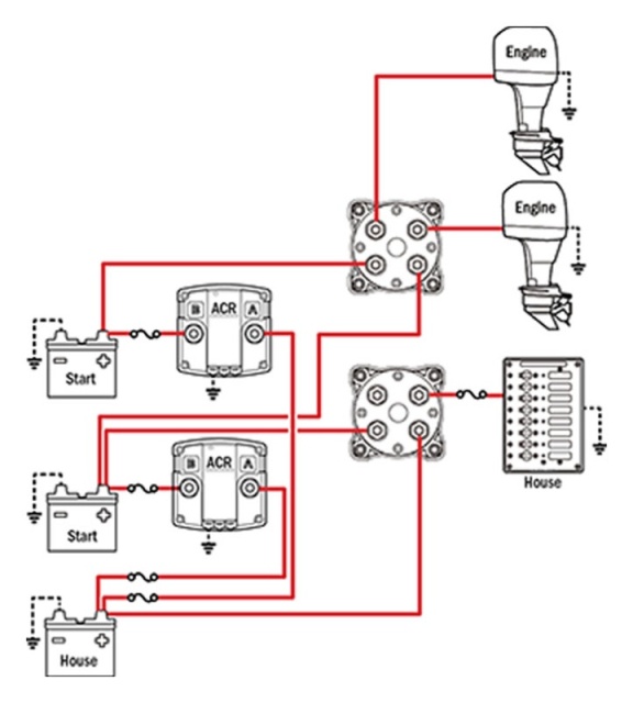
This seems like the most logical set-up to my mind, but I'm drawing from a vast wealth of ignorance.
In this scenario it looks like each alternator charges it's own start battery.
Each Start battery is connected to the House battery via it's own SI-ACR and should(?) be isolated using the start isolation circuit on the center tab (not shown) to prevent voltage spikes on the house circuit during cranking.
Based on this, I assumed the 14.5v each alternator puts out would be shared between it's own Start battery and the House battery anytime when underway.
Seems once the Start batteries were topped-up, all the alternator charge would continue to be sent to the House battery, but you know what they say about assuming...
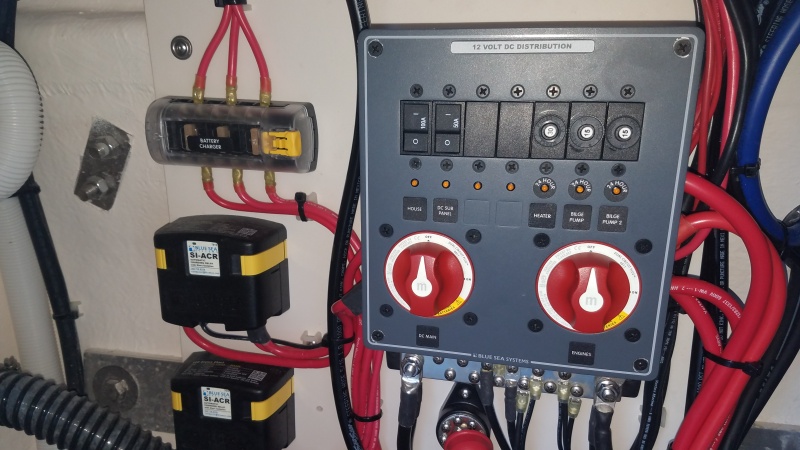
At first glance, C-Shalom's wiring looks like it could be similar to the diagram except for the additional 3 feeds from the ProNautic 1220P charger.
Checking individual voltages underway and under shore power shows almost exactly as you described.
After a night of charging, the House battery and Starboard Start battery showed 13.2v while the Port Start battery stayed at 12.58v.
With the engines running, the Port Start battery was now being charged by the alternator at 14.7v and the other two batteries dropped to 13.03v.
Hopefully someone can shed a little light on how these components are actually wired and why they're wired that way? |
|
| Back to top |
|
|
BillE
Joined: 09 Jun 2016
Posts: 283
City/Region: Nashville
State or Province: TN
C-Dory Year: 2004
C-Dory Model: 25 Cruiser
Vessel Name: TBD
Photos: BillE
|
| Posted: Mon Oct 08, 2018 12:28 pm Post subject: |
|
|
Are you having electrical issues with your new Tomcat?
_________________
Bill & Sherry C-25 sold 2020, next? |
|
| Back to top |
|
|
thataway
Joined: 02 Nov 2003
Posts: 20988
City/Region: Pensacola
State or Province: FL
C-Dory Year: 2007
C-Dory Model: 25 Cruiser
Vessel Name: thataway
Photos: Thataway
|
| Posted: Mon Oct 08, 2018 2:40 pm Post subject: |
|
|
beautiful wiring in the boat and diagram....too bad its is not wired properly!
There are any number of possibilities--you are going to have to do some diagnostic work...or take the boat back to the dealer and demand that it be corrected. This may entail chasing every wire and then checking every switch.
The port motor is connected to charge the port start battery only--it also could be a defective switch. Also could be incorrectly wired/defective ACR. The starboard engine is not charging either battery. Again probably a simple wiring error.
The ACR should be active when the battery charger is working. So I would start looking at the ACRs and how they are wired..
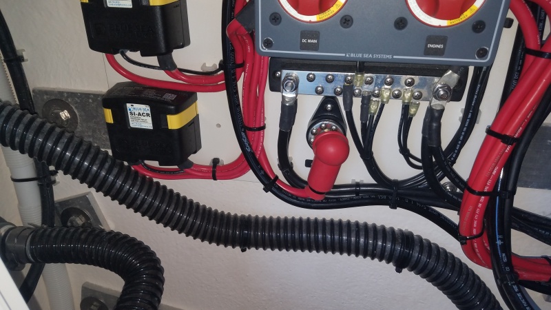
It also looks as if the battery charger leads are going to the ACR, instead of the battery.
There could be a problem with the starboard alternator, as well as the ACR or wiring. It may just be a simple wiring problem.
Sometimes looking at the circuit and then at the wiring there is an obvious mistake.
Do your engines have two charging outputs? Suzuki should have--thus making the ACR redundant, and perhaps complicating the charging--certainly not allowing the best features of the battery charger to be used...
Many boats only are wired with only one engine charging the house battery, so It may be that this is the case, and there is an error in the wiring. Where the error is--may be obvious--may not--but the volt meter will tell--label the wires and check voltages as well as doing your own diagram. |
|
| Back to top |
|
|
JMacLeod
Joined: 26 Jun 2018
Posts: 173
City/Region: Stuart
State or Province: FL
C-Dory Year: 2018
C-Dory Model: 255 Tomcat
Vessel Name: C-Shalom
Photos: JMacLeod
|
| Posted: Mon Oct 08, 2018 8:14 pm Post subject: |
|
|
| BillE wrote: | | Are you having electrical issues with your new Tomcat? |
Hi Bill.
I was thinking possibly as much chance user error as an actual problem until Bob gave me a chuckle.
| thataway wrote: | | beautiful wiring in the boat and diagram....too bad its is not wired properly! |
| thataway wrote: | There are any number of possibilities--
...
Do your engines have two charging outputs? Suzuki should have--thus making the ACR redundant, and perhaps complicating the charging--certainly not allowing the best features of the battery charger to be used... |
Yes, I discovered that feature listed for the DF150 on the mfg site while searching for alternator specs and amps.
(Which on a sidenote was impressive. At an idle 1000 rpm they can produce 35 amps each, and over 40 amps each below 2000 rpm. Seems like quite a bit of juice is getting underutilized.)
So between two dual circuit switches that can combine, two dedicated SI-ACRs, 4 available alternator outputs, and 1 to 3 charger outputs, there really are a lot of ways to skin this cat, and only the technician knows which way he chose.
I'll start with testing the ACRs as you suggested, and see where that path leads.
Besides the extra alternator outputs making the ACRs redundant, so does the 3 separate feeds from the shore charger.
It looks like you could choose to wire each battery directly to it's own charging feeds and eliminate the ACRs, or use the ACRs as intended and only need a single feed from each charging source for all battery banks.
It'll be a few days before I can go down and see her, so I have some time to read through the manuals again and try and make it make sense to my brain.  |
|
| Back to top |
|
|
thataway
Joined: 02 Nov 2003
Posts: 20988
City/Region: Pensacola
State or Province: FL
C-Dory Year: 2007
C-Dory Model: 25 Cruiser
Vessel Name: thataway
Photos: Thataway
|
| Posted: Mon Oct 08, 2018 8:45 pm Post subject: |
|
|
With that charger you want to wire each battery separately. Put the temp sensor probe on the house battery (You will probably want to add a second house battery in parallel).
I would get rid of the ACR, because they will be active during the battery charger usage and defeat some of the features of the individual battery charging of the ProNautic charger.
The ACR combine when the voltage reaches a certain level--usually 13.7 volts, rather than the battery being charged. The outboards go right up to 14.4/.5 volts rapidly--before the battery is fully charged.
Both the ACR and independent charge circuits off the motor will Isolate the batteries. Another option is to split two house batteries (when you get them) and then charge off each port and starboard motors, Then select one two or all for use of the house bank. Or dedicate one to electronics, stereo, lights etc. The other to the refrigeration--which is often the largest draw on the Tom Cat. Lots off ways to do this, and choices.
From what you have written, I suspect that the intent was to charge the house bank, only off one outboard. Not sure if the wiring was done at the factory or at dealer. I can see the factory putting in the ACR, not being aware you were going to use the Suzuki engines...then the engine wiring would have been done by dealer.
Don't remember if you put in a monitoring system or not--and that may reflect on what choices you make on the house bank. |
|
| Back to top |
|
|
JMacLeod
Joined: 26 Jun 2018
Posts: 173
City/Region: Stuart
State or Province: FL
C-Dory Year: 2018
C-Dory Model: 255 Tomcat
Vessel Name: C-Shalom
Photos: JMacLeod
|
| Posted: Tue Oct 09, 2018 1:41 pm Post subject: |
|
|
| thataway wrote: | | With that charger you want to wire each battery separately. Put the temp sensor probe on the house battery (You will probably want to add a second house battery in parallel). |
We definitely want a bigger house bank, also solar and some way to monitor usage or at least SoC, as well as considerations for the Honda 2200i.
I've been kicking around ideas of putting an AGM shelf in the top of the water heater cabinet and/or the top of the galley cabinet versus adding more weight to the transom with another flooded 27 or golf cart batteries versus some of the other suggestions on the forum, including moving the batteries down into the sponsons.
There's so many options available it's causing a bit of analysis paralysis.
| thataway wrote: | I would get rid of the ACR, because they will be active during the battery charger usage and defeat some of the features of the individual battery charging of the ProNautic charger.
The ACR combine when the voltage reaches a certain level--usually 13.7 volts, rather than the battery being charged. The outboards go right up to 14.4/.5 volts rapidly--before the battery is fully charged. |
These particular SI-ACRs will combine as low as 13.0v if sensed for a continuous 90 sec... which I guess means that immediately after charging, the surface charge will keep them combined until enough of a discharge knocks it below 13v?
Seems even more of a reason to use the start isolation feature if using these ACRs.
As much as I hate wasting brand new fancy electronic gizmos, I have to agree. If we purchase one or two Suzuki harnesses I can't think of any useful purpose left for the ACRs. 
| thataway wrote: | | Both the ACR and independent charge circuits off the motor will Isolate the batteries. Another option is to split two house batteries (when you get them) and then charge off each port and starboard motors, Then select one two or all for use of the house bank. Or dedicate one to electronics, stereo, lights etc. The other to the refrigeration--which is often the largest draw on the Tom Cat. Lots off ways to do this, and choices. |
I think we covered that above with analysis paralysis.  
We could purchase one harness, and another flooded house battery, or one harness and replace the flooded house with 2 AGMs, or two harnesses and one AGM in the cabin that charges independently from the flooded house bank.
I guess I need to weigh the expense, effort, and practicality of each option before proceeding.
| thataway wrote: | From what you have written, I suspect that the intent was to charge the house bank, only off one outboard. Not sure if the wiring was done at the factory or at dealer. I can see the factory putting in the ACR, not being aware you were going to use the Suzuki engines...then the engine wiring would have been done by dealer.
Don't remember if you put in a monitoring system or not--and that may reflect on what choices you make on the house bank. |
Haven't decided on a monitor yet because I haven't researched enough real world experience to know which features are useful versus hype, i.e. $15 diy LCDs compared to $XXX namebrand marine gizmos. |
|
| Back to top |
|
|
thataway
Joined: 02 Nov 2003
Posts: 20988
City/Region: Pensacola
State or Province: FL
C-Dory Year: 2007
C-Dory Model: 25 Cruiser
Vessel Name: thataway
Photos: Thataway
|
| Posted: Tue Oct 09, 2018 6:57 pm Post subject: |
|
|
There are features on the various monitors which are pluses. I have used the Victron 702 type mostly. The volt meters are fine for gross management, and if you have periods where the batteries have been truly "at rest".
I put at 2 AGM group 31's behind the water heater/ and that area in my Tom Cat and the first 25. This one I sprung for the more expensive Li ion, because of the weight and volume, plus I have been itching to try one. Not practical if you want to combine all in one large bank. But using the Suzuki second charge circuit plus a dedicated 10 to 20 amp charger for the Li ion, it would work fine for refer/freezer combo. If you use the boat much and keep it for at least 8 years the economics work out closely. Solar can be easily adapted to the Li ion as well as AGM, but I would keep them separate if you go that way. |
|
| Back to top |
|
|
journey on
Joined: 03 Mar 2005
Posts: 3598
City/Region: Valley Centre
State or Province: CA
C-Dory Year: 2005
C-Dory Model: 25 Cruiser
Vessel Name: journey on
Photos: Journey On
|
| Posted: Tue Oct 09, 2018 8:32 pm Post subject: |
|
|
So, Bob, you're on to LFP batteries for your 25? If so, I have some questions.
How many amp-hrs do you have? What are you using to charge them? What brand are they? How much do they weigh?
Here's a blog from someone who got LFP batteries back in 2011 (a rich one, I guess): LFP battery lessons. The person has several good lessons on lifetime vs temperatures, charging, discharge cycle, etc. Well worth reading.
And here is an explanation on how to balance a battery: battery balancing.
Boris |
|
| Back to top |
|
|
thataway
Joined: 02 Nov 2003
Posts: 20988
City/Region: Pensacola
State or Province: FL
C-Dory Year: 2007
C-Dory Model: 25 Cruiser
Vessel Name: thataway
Photos: Thataway
|
| Posted: Tue Oct 09, 2018 11:20 pm Post subject: |
|
|
Hi Boris,
The link and another RVer who had Li Fo PO4 for a number of years is one I have followed for some time. I have also read a number of articles of others who have used them on boats and in solar installations.
The Li Fe PO4 battery does not have the risks of fire or explosion that some of the other Li ion batteries pose. They can be discharged 90% over 3000 cycles and still maintain 80% of capacity and have been discharged over 5000 cycles in some controlled environments.
I have "Battle Born" batteries. I dealt directly with the company and they answered all questions and were prompt in delivery.
100 Amp Hour, 12 Volt Battery
LiFePO4 Chemistry
3000- 5000 Cycles*
100 Amp Continuous Current
200 Amp Surge Current (30 Seconds)
1/2 second surge for higher loads
Drop in Replacement for Lead Acid Batteries
Acceptable Voltages 14.4 14.6 for bulk charging
10 Year Warranty
Designed and Assembled in the USA
12.75 x 6.875 x 9 (L x W xH)
29 lbs
These are internally balanced, and do not appear to have the requirement of annual re-balancing that the larger banks do.
I have been charging with the West Marine 30 amp charger using Anderson pole connectors for the bulk charge and A 10 AMP 12 volt charger from an Internet supplier (I don't have the brand handy right now) which is designed for higher voltage adsorption and float patterns. It has readout of both amps and volts on its screen. I monitor the system with a Victron 700 BM. I have used it only on the chest type refrigerator and freezer. I have isolated this battery and have a double pole on off on switch for the selection of the house bank or the Li ion battery to run the reefer/freezer. |
|
| Back to top |
|
|
|
|
You cannot post new topics in this forum
You cannot reply to topics in this forum
You cannot edit your posts in this forum
You cannot delete your posts in this forum
You cannot vote in polls in this forum
You cannot attach files in this forum
You cannot download files in this forum
|
|
 Search
 Private Messages
 Profile
 Log in
 Register
 Help
Help
