| View previous topic :: View next topic |
| Author |
Message |
ferret30
Joined: 22 Mar 2011
Posts: 569
City/Region: Seattle
State or Province: WA
C-Dory Year: 2006
C-Dory Model: 22 Cruiser
Vessel Name: Lily Pad
Photos: Lily Pad
|
 Posted: Tue Jun 19, 2012 7:14 pm Post subject: 30A shore power install recap Posted: Tue Jun 19, 2012 7:14 pm Post subject: 30A shore power install recap |
 |
|
I finished installing a shore power system a couple weeks ago and finally got the pictures off my phone so I thought I'd post them along with a description of the system.
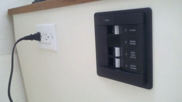
* Blue Sea 1214 360 Series AC panel
* Blue Sea 4027 panel back cover
* Marinco 301EL-B 30A inlet
* 2x Leviton 7599-W GFCI receptacles
* 10/3 stranded tinned wire for inlet to panel
* 12/3 stranded tinned wire for panel to receptacles
* #10 green stranded tinned wire for shore power ground to DC neutral
I was originally going to purchase a Blue Sea 8099 system, but it was quite a bit wider, and had a 3rd 15A breaker I would never use. The 1214 has a square form factor and only 2 branch breakers, and the switches don't project from the face of the panel, so I thought it would be more robust.
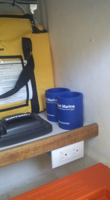
I chose to install the panel below the helm seat, directly across from the DC panel. This location is out of the way, easy to access from both sides, and open enough that I was able to use a jigsaw to make the cuts. Sitting in the driver's seat, the panel isn't noticeable at all. I installed the primary cabin GFCI a little to the side of the panel using an "old work" blue Carlon box. The second GFCI is mounted to the underside of the galley cabinet shelf using a special j-box with 'ears' that allowed it to be screwed to the shelf. I had to cut the cover plate along one edge so it would still mount in this configuration (I don't have pics of the second receptacle yet). The receptacle is out of the way, mounted at the aft end of the shelf where it can be used to run the charger, and also an aux item like a dehumidifier.
Panel and cabin GFCI under front of helm seat base:

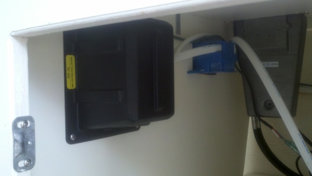
Back of panel inside helm seat base compartment. Note that the wire on the right isn't installed yet. I don't leave wires hanging loose running through compartments!:

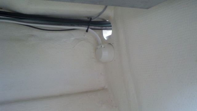
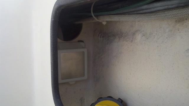
Backside of 30A inlet under galley counter:

Inlet installed in starboard gunnel shelf through bulkhead:

Many thanks to Les at EQ who gave me valuable advice.
See this Don Casey article for more in depth guidance than I covered here: http://www.boatus.com/boattech/casey/safe-shorepower.asp |
|
| Back to top |
|
 |
jingram
Joined: 08 Feb 2010
Posts: 41
City/Region: Salem
State or Province: OR
|
| Posted: Wed Jun 20, 2012 12:04 am Post subject: |
|
|
| Really clean install... looks great! |
|
| Back to top |
|
|
bshillam
Joined: 21 Aug 2007
Posts: 783
City/Region: Bellingham
State or Province: WA
C-Dory Year: 1981
Vessel Name: Heaven To Me
Photos: My Heaven
|
| Posted: Wed Jun 20, 2012 8:40 am Post subject: Love the install |
|
|
Mikey likely. 
Where did you put the second electrical outlet? Do you have pics on how you ran the wiring? |
|
| Back to top |
|
|
ferret30
Joined: 22 Mar 2011
Posts: 569
City/Region: Seattle
State or Province: WA
C-Dory Year: 2006
C-Dory Model: 22 Cruiser
Vessel Name: Lily Pad
Photos: Lily Pad
|
| Posted: Wed Jun 20, 2012 1:55 pm Post subject: |
|
|
| I'll take a pic of the other outlet when I get a chance. The wires from the inlet (10/3 and #10 ground to DC neutral bus) run through the wire hangers (zip ties) along with the house power and motor controls. The first outlet is right next to the panel. The second outlet is in the galley cabinet under the shelf next to the bulkhead, facing toward the opening so it's easy to access but still out of the way. The cable to this outlet runs under that shelf along the back, along to the helm seat cabinet where it runs up and joins the larger bundle. I used some of those white plastic cable clamps to suspend that cable tightly under the shelf so it doesn't catch on things. |
|
| Back to top |
|
|
ferret30
Joined: 22 Mar 2011
Posts: 569
City/Region: Seattle
State or Province: WA
C-Dory Year: 2006
C-Dory Model: 22 Cruiser
Vessel Name: Lily Pad
Photos: Lily Pad
|
| Posted: Wed Jun 20, 2012 2:24 pm Post subject: |
|
|
My next step is to pick a charger and install it. I was interested in ProMariner, but the 5' charger leads are too short, and I think the $30 extensions they sell are kind of a gimmick. I called their tech support and the guy that answered my email and phone call seemed pretty unhelpful. Most chargers would require a change in gauge for a longer run, and the guy couldn't explain why it's necessary to use their extensions. He only would say that modifying the leads would void the warranty.
I'd prefer a charger that lets you wire up your own leads and select gauge based on wire run. |
|
| Back to top |
|
|
ferret30
Joined: 22 Mar 2011
Posts: 569
City/Region: Seattle
State or Province: WA
C-Dory Year: 2006
C-Dory Model: 22 Cruiser
Vessel Name: Lily Pad
Photos: Lily Pad
|
| Posted: Fri Jun 22, 2012 3:02 pm Post subject: |
|
|
I broke the image links when I renamed the album so I'm re-posting them. Also, I finally took a picture of the outlet in the galley cabinet.
Panel and cabin GFCI under front of helm seat base:
Back of panel inside helm seat base compartment. Note that the wire on the right isn't installed yet. I don't leave wires hanging loose running through compartments!:
Backside of 30A inlet under galley counter:
Galley cabinet outlet for charger, dehumidifier, etc.:
Inlet installed in starboard gunnel shelf through bulkhead:
 |
|
| Back to top |
|
|
Ray
Joined: 13 Dec 2011
Posts: 271
City/Region: Pamlico River
State or Province: NC
C-Dory Year: 2007
C-Dory Model: 25 Cruiser
Vessel Name: Seaweed
Photos: Seaweed
|
| Posted: Fri Jun 22, 2012 5:31 pm Post subject: |
|
|
| Please consider putting a breaker right near the shore power inlet! (experience) |
|
| Back to top |
|
|
ferret30
Joined: 22 Mar 2011
Posts: 569
City/Region: Seattle
State or Province: WA
C-Dory Year: 2006
C-Dory Model: 22 Cruiser
Vessel Name: Lily Pad
Photos: Lily Pad
|
| Posted: Fri Jun 22, 2012 5:37 pm Post subject: |
|
|
| Ray wrote: | | Please consider putting a breaker right near the shore power inlet! (experience) |
The inlet to panel (breaker) run is less than 5 feet, using 10/3 stranded wire. An additional breaker is only required if the inlet to panel run is more than 10 feet.
Why would there be a need for another breaker? And where would this breaker go, in another AC panel? Please explain. |
|
| Back to top |
|
|
thataway
Joined: 02 Nov 2003
Posts: 21588
City/Region: Pensacola
State or Province: FL
C-Dory Year: 2007
C-Dory Model: 25 Cruiser
Vessel Name: thataway
Photos: Thataway
|
| Posted: Fri Jun 22, 2012 6:02 pm Post subject: |
|
|
double post.
_________________
Bob Austin
Thataway
Thataway (Ex Seaweed) 2007 25 C Dory May 2018 to Oct. 2021
Thisaway 2006 22' CDory November 2011 to May 2018
Caracal 18 140 Suzuki 2007 to present
Thataway TomCat 255 150 Suzukis June 2006 thru August 2011
C Pelican; 1992, 22 Cruiser, 2002 thru 2006
Frequent Sea; 2003 C D 25, 2007 thru 2009
KA6PKB
Home port: Pensacola FL
Last edited by thataway on Fri Jun 22, 2012 6:06 pm; edited 1 time in total |
|
| Back to top |
|
|
thataway
Joined: 02 Nov 2003
Posts: 21588
City/Region: Pensacola
State or Province: FL
C-Dory Year: 2007
C-Dory Model: 25 Cruiser
Vessel Name: thataway
Photos: Thataway
|
| Posted: Fri Jun 22, 2012 6:04 pm Post subject: |
|
|
| What you have done corresponds to ABYC standards, and is a good installation. One question which might be asked is about a Gavlvanic isolator. As long as you are not leaving the boat in the water with the AC circuit, and no thru hull fittings bonded etc--then that is probably not necessary. The use of a battery charger is what brings up that question. |
|
| Back to top |
|
|
ferret30
Joined: 22 Mar 2011
Posts: 569
City/Region: Seattle
State or Province: WA
C-Dory Year: 2006
C-Dory Model: 22 Cruiser
Vessel Name: Lily Pad
Photos: Lily Pad
|
| Posted: Fri Jun 22, 2012 6:13 pm Post subject: |
|
|
Bob, the boat is in a marina. When the Suzuki is tilted up, the lower unit is out of the water, but the fixed part of the motor that bolts to the transom is in the water.
Do you have an isolator on your boat? Is the amperage supposed to match the panel rating, i.e. my panel/inlet is 30A so I'd use a 30A galvanic isolator?
PS I do have a #10 green stranded wire from the AC ground to the DC neutral, as explained by Don Casey in his shore power article. And I have made certain that my AC neutral and ground circuits are isolated on the boat (they probably bond at the marina's AC panel. |
|
| Back to top |
|
|
Robert H. Wilkinson
Joined: 26 Jan 2011
Posts: 1281
City/Region: Port Ryerse
State or Province: ON
Vessel Name: Romakeme IV
Photos: Romakeme IV
|
| Posted: Sun Jun 24, 2012 12:09 am Post subject: 30amp shore power |
|
|
Hi Ferret, if you are looking to get a galvanic isolation transformer - here are the websites for 3 different manufacturers.
www.mastervolt.com
www.newmarpower.com
www.charlesindustries.com
If you are in a marina with a long electrical run you can also get 1 that includes a voltage boosting circuit.
I just happened to be reading the June issue of the Canadian Yachting magazine. They have a writeup about shore power systems in this issue. Don't know if you have access to that magazine in the US or not.
Regards, Rob
_________________
Talk to me and I will listen-- but if its not about boats or fishing all I will hear is bla,bla,bla,yada,yada,zzzzzzzz |
|
| Back to top |
|
|
thataway
Joined: 02 Nov 2003
Posts: 21588
City/Region: Pensacola
State or Province: FL
C-Dory Year: 2007
C-Dory Model: 25 Cruiser
Vessel Name: thataway
Photos: Thataway
|
| Posted: Sun Jun 24, 2012 6:03 pm Post subject: |
|
|
I don't think you need an isolation transformer (although these are nice to have). If there is excess electrolysis as one boat had in another forum, probably due to miss wiring in the marina, then I would suggest an isolation transformer. If you are going foreign, then the transformer could both step down the current and isolated (but not affect the frequency).
Generally the common point is the engine block--which ends up being also the negative at the battery. You don't want other ground/bonding/green wire connections.
No, I do not have a galvanic isolator on my 22, I did on the 25 and the Tom Cat. The 22 is mainly kept on a lift or trailer, and not hooked up to shore power on a regular basis.
Yes, there is always going to be the point of contact with the water of the outboard bracket.
The 30 amp Guest Galvanic isolator would be the correct size for your setup. |
|
| Back to top |
|
|
ferret30
Joined: 22 Mar 2011
Posts: 569
City/Region: Seattle
State or Province: WA
C-Dory Year: 2006
C-Dory Model: 22 Cruiser
Vessel Name: Lily Pad
Photos: Lily Pad
|
| Posted: Mon Oct 08, 2012 2:02 pm Post subject: |
|
|
Last week I installed a galvanic isolator. There a 3 types of isolators (as far as I know):
* The cheapest ones are basically 4 diodes, and are completely passive. These aren't up to code since they can quietly fail and open the ground connection to shore with no indication.
* More expensive models provide a remote monitoring panel that indicates when things are working properly, or when the unit has failed due to a short to ground (etc.). The problem is, if the unit fails while you are away from your boat, you can start sending line voltage into the water, start a fire, all kinds of fun things. I want to keep the boat on shore power and not worry about it...
* A fail-safe model has the same basic function as the above two, but in the case of failure of the diodes due to a large current, the unit will end up shorting the input to the output. If I had a ground fault that sent line voltage into the ground wire, and for whatever reason didn't trip a GFCI or breaker, the fail safe unit would ensure that the ground was preserved through and after the fault.
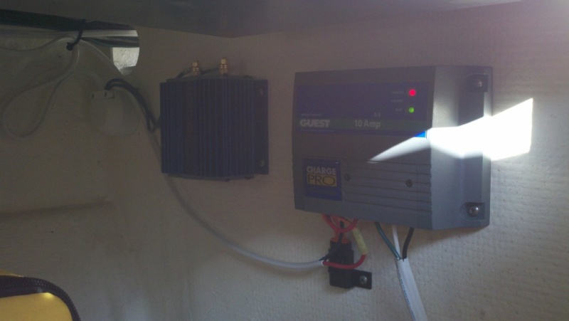
The model in the picture (background) is a GUEST 30A Fail-Safe model 4531001.
The isolator is mounted right next to the inlet. The 10/3 stranded wire from the breaker panel enters the inlet case, but the ground wire does a U-turn and exits the case and connects to the isolator. Another wire from the isolator runs back into the inlet case and connects to the ground stud. I did it this way since there was enough room in the inlet's cable clamp, and I didn't want to cut open the mains cable sheathing outside the inlet body to split off the ground wire. |
|
| Back to top |
|
|
ferret30
Joined: 22 Mar 2011
Posts: 569
City/Region: Seattle
State or Province: WA
C-Dory Year: 2006
C-Dory Model: 22 Cruiser
Vessel Name: Lily Pad
Photos: Lily Pad
|
| Posted: Mon Oct 08, 2012 2:11 pm Post subject: |
|
|
I installed a Guest 2610A 5/5 charger last week as well (pictured in the previous post). I picked that model specifically because it has terminals for all in/out wires. Most chargers under $150 tend to have short cables permanently installed (i.e. 5' AC cable and 5' output lines).
This model also let me hard wire the charger to the GFCI receptacle below, rather than having it plug in.
For extra safety, I installed inline fuses at both ends of the positive line to the battery (15A). The charger has output protection, so probably not necessary, but I had an extra fuse holder. I used 12/2 stranded wire from the charger to the battery. |
|
| Back to top |
|
|
|
 Search
 Private Messages
 Profile
 Log in
 Register
 Help
Help
